


114
Cycle Time Settings Section 5-6
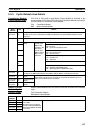
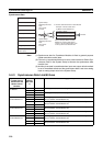
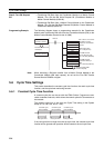
Step 2: Turn ON Request
Bit
• Transferring DM Data from the Coordinator Module to a Motion Control
Module: Turn ON the DM Write Request Bit (Coordinator Module to
Motion Control Module) (A530.00).
• Transferring DM Data from a Motion Control Module to the Coordinator
Module: Turn ON the DM Read Request Bit (Motion Control Module to
Coordinator Module) (A530.01).
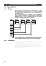
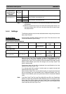
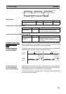
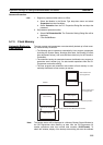
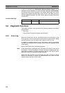
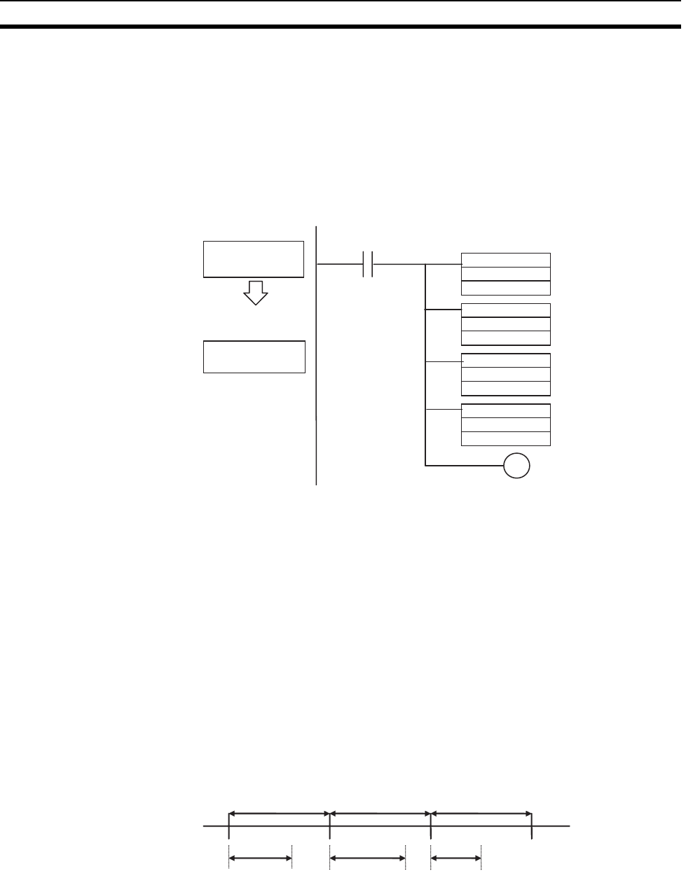
Programming Example The following diagram shows a programming example for the Coordinator
Module when transferring DM data from the Coordinator Module (CM) to the
Motion Control Module mounted to slot #1 (MM).
Note When executing a DM data transfer from a Motion Control Module to the
Coordinator Module (DM read request), do not set the First DM Transfer
Source Word to D30000 or higher
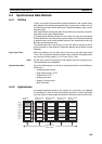
5-6 Cycle Time Settings
This section describes the constant cycle time function, the watch cycle time
function, and the cycle time monitoring function.
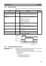
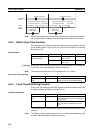
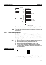
5-6-1 Constant Cycle Time Function
A constant cycle time can be set with the FQM1 Series. Programs are exe-
cuted at standard intervals, which allows the control cycles for Servomotors to
be constant.
The constant cycle time is set using the Cycle Time setting in the System
Setup (0.1 to 100.0 ms, unit: 0.1 ms).
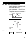
If the real cycle time is longer than the set cycle time, the constant cycle time
function will be ignored and operation will be based on the real cycle time.
CM
D00200 to D00299
MM
D00100 to D00199
@MOV
#0001
A531
@MOV
#0064
A534
@MOV
#00C8
A533
@MOV
#0064
A532
㨃000.00
Transfer of 100 words
of DM data
Set to slot #1, the slot for
the Motion Control
Module for the DM data
transfer.
DM Transfer Size:
Set to 100 (64 hex).
First DM Transfer
Source Word (in CM):
Set to C8 Hex (D00200).
First DM Transfer
Destination Word (in
MM):
Set to 64 Hex (D00100).
A530.00 (CM to MM
transfer request)
Constant cycle
time (enabled)
Constant cycle
time (enabled)
Constant cycle
time (enabled)
Real cycle time Real cycle timeReal cycle time