


200
Functions for Servo Drivers Compatible with Absolute Encoders Section 7-7
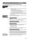
7-7-3 Data Format of Absolute Encoder Output
The format of data from a Servo Driver compatible with an absolute encoder
supported by the Motion Control Module is as follows:
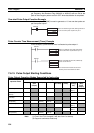
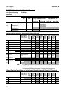
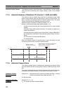
Serial Data Specification
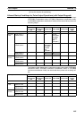
Data Format
Note (1) The “P” is in ASCII. It is 50 hex in hexadecimal.
(2) The range of No. of rotations that can be received by the Motion Control
Module is between +65,535 to
−65,535.
(3) For details of the data on the number of multi-turns received from a Servo
Driver, please check the manual of the Servo Driver in use.
(4) Set the System Setup’s Counter 1 Counter operation to either an abso-
lute linear (CW
−) or absolute linear (CW+) counter corresponding to the
setting of reverse rotation mode on the Servo Driver in use.
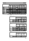
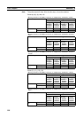
(5) When the mode where the data on the number of rotations is output only
in the + direction is set in the absolute encoder multi-turn limit setting, the
data received by the Motion Control Module is handled as described be-
low according to the setting of Counter 1 Counter operation in the System
Setup.
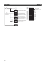
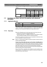
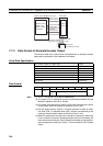
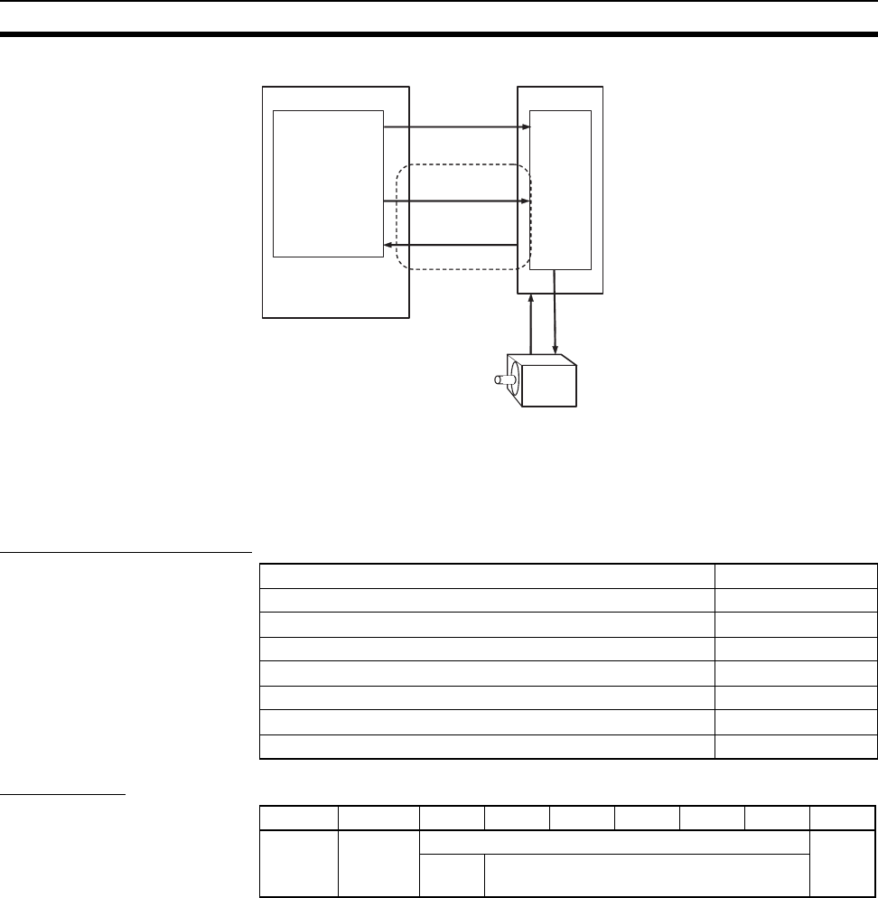
Motion Control Module Servo driver
Speed
control
Position control,
(SPED, ACC,
PULS or PLS2
instruction)
SEN signal
Power cable
(U, V, W)
Absolute encoder
signal (line driver)
Servomotor
with Absolute encoder
Analog output
(Speed command)
−10 to 10 V, etc.
Absolute
encoder data
Pulse output
The number of digits for rotation data 5 digits
Data transmitting method Asynchronous
Baud rate 9,600 bits/s
Start bit 1 bit
Stop bit 1 bit
Parity Even numbers
Character code ASCII 7 bits
Data format 8 characters
Byte +0 +1 +2 +3 +4 +5 +6 +7
P (See
note 1.)
Rotation data CR
Sign
(+ or −)
Integer (5-digit decimal)