


70
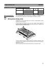
Wiring Module Connectors Section 3-3
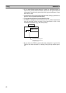
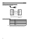
Note Connect the voltage input (+) and the current input when using with a current
input between 4 and 20 mA.
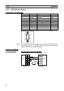
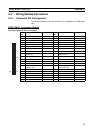
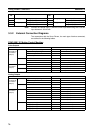
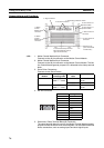
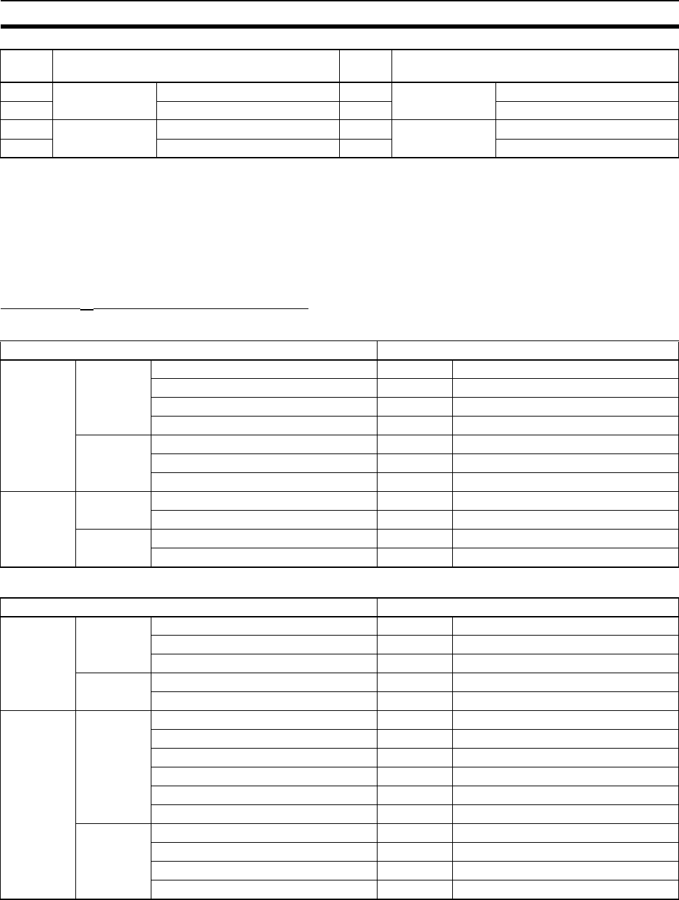
3-3-2 External Connection Diagrams
The connections with the Servo Drivers, the main type of device connected,
are outlined in the following tables.
FQM1-MM@21 Motion Control Modules
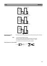
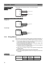
Pulse Outputs
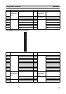
Analog Outputs
33 Analog input Voltage input (+) 34 Analog input Current input (See note.)
35 Voltage input (−) 36 (Current input common)
37 Analog output 1 Voltage output (+) 38 Analog output 2 Voltage output (+)
39 Voltage output (−) 40 Voltage output (−)
Pin.
No.
Name Pin.
No.
Name
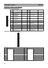
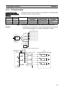
Motion Control Module W-series Servo Driver
General-
Purpose I/O
Connector
(26 pin)
Inputs Positioning Completed Signal INP1 Positioning completed output
Origin Proximity Input Signal
CCW Limit Input
CW Limit Input
Outputs Servo ON RUN RUN command input
Alarm reset RESET Alarm reset input
Error Counter Reset ECRST Error Counter Reset Input
Special I/O
Connector
(40 pin)
Inputs Phase Z LD+ +Z Encoder output phase Z
Phase Z LD−−Z Encoder output phase Z
Outputs Pulse output CCW CCW Forward pulse
Pulse output CW CW Reverse pulse
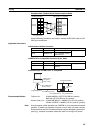
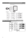
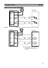
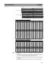
Motion Control Module W-series Servo Driver
General-
purpose I/O
Connector
(26 pin)
Inputs Origin Proximity Input Signal
CCW Limit Input
CW Limit Input
Outputs Servo ON RUN Run command input
Alarm reset RESET Alarm reset input
Special I/O
Connector
(40 pin)
Inputs Phase A LD+ +A Encoder output phase A
Phase A LD−−A Encoder output phase A
Phase B LD+ +B Encoder output phase B
Phase B LD−−B Encoder output phase B
Phase Z LD+ +Z Encoder output phase Z
Phase Z LD−−Z Encoder output phase Z
Outputs Analog output 1 (+) REF Speed command input
Analog output 1 (−) AGND Speed command input
Analog output 2 (+) TREF Torque command input
Analog output 2 (−) AGND Torque command input