


42
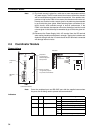
Motion Control Modules Section 2-4
Pulse Inputs and Analog
I/O Specifications
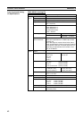
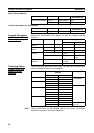
FQM1-MMA21 (Analog I/O)
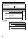
Item Specifications
Pulse
inputs
Number of counters 2
Counter operations Linear counter, circular counter
Input signals Two words each for phase A, phase B, and phase Z.
Signal levels CH1: 24 V DC, line-driver
CH2: Line-driver
Input method Phase differential ×1
Phase differential ×2
Phase differential ×4
Increment/decrement
Pulse + direction
Counting speed Voltage 50 kHz
Line-driver 50 k Hz/500k Hz (phase
differential × 4, 2 MHz)
Absolute Servo
Driver interfaces
2
SEN output specifications: 5 V PNP output, output
current 5 mA
When SEN signal is output to Servo Driver, Servo
Driver will transmit the number of encoder's rotations
to this Module. After that, it transmits pulse train cor-
responding to displacement of the number of rota-
tions to the Module.
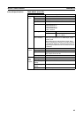
Analog
input
Number of analog
inputs
1
Input signals Voltage inputs:
−10 to 10 V
0 to 10 V
1 to 5 V
0 to 5 V
Current inputs:
4 to 20 mA
Resolution −10 to 10 V: 14 bits (1/16,000)
0 to 10 V: 13 bits (1/8,000)
0 to 5 V: 12 bits (1/4,000)
1 to 5 V/4 to 20 mA: 12 bits (1/4,000)
Accuracy (FS) Voltage input:
± 0.2% (23 ± 2°C)
± 0.4% (0 to 55°C)
Current input:
± 0.4% (23 ± 2°C)
± 0.6% (0 to 55°C)
Conversion speed 40 µs max./input
Total: 1.5 ms max.
Analog
outputs
Number of outputs 2
Output signal −10 to 10 V, 0 to 10 V, 1 to 5 V, 0 to 5 V
Resolution −10 to 10 V: 14 bits (1/1,0000)
0 to 10 V: 12 bits (1/4,000)
0 to 5 V: 12 bits (1/4,000)
1 to 5 V: 12 bits (1/4,000)
Accuracy (FS) ± 0.3% (23 ± 2°C) ± 0.5% (0 to 55°C)
Conversion speed 40 µs max./output
Total: 200 µs max.