


338
System Setup, Auxiliary Area Allocations, and Built-in I/O Allocations Appendix C
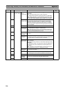
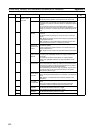
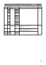
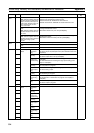
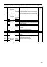
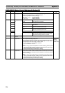
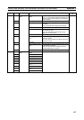
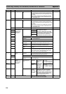
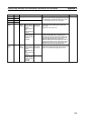
Address Bits Name Function Controlled by
A564 00 Analog Output 1 Conversion Enable
Bit
ON: Enables D/A conversion (enables analog output).
OFF: Disables DA conversion (analog values output
according to Output Stop Function specification in Sys-
tem Setup).
Note This bit is cleared when the Modules operating
mode is changed between RUN or MONITOR mode
and PROGRAM mode.
User
01 to 15 Reserved --- ---
A565 00 Analog Output 2 Conversion Enable
Bit
ON: Enables D/A conversion (enables analog output).
OFF: Disables DA conversion (analog values output
according to Output Stop Function specification in Sys-
tem Setup).
Note This bit is cleared when the Modules operating
mode is changed between RUN or MONITOR mode
and PROGRAM mode.
User
01 to 15 Reserved --- ---
A570 00 Adjustment Mode
Command Bits
(Effective only
when A575 is
5A5A hex.)
Adjustment Enable Analog Input OFF: Adjustment disabled.
ON: Adjustment enabled.
When one of these bits is turned ON,
the default value (offset or gain value)
corresponding to the selected I/O signal
range is transferred to Adjustment
Mode Monitor Area (A572 and A573).
User
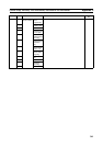
01 Reserved
02 Analog Out-
put 1
03 Analog Out-
put 2
04 to 06 Reserved
07 Adjustment Mode
Specifier
OFF: Offset adjustment
ON: Gain adjustment
08 to 11 Reserved
12 Adjustment Value
Increment
While this bit is ON, the offset or gain value will be
incremented by one resolution unit each 0.5 ms.
13 Adjustment Value
Decrement
While this bit is ON, the offset or gain value will be dec-
remented by one resolution unit each 0.5 ms.
14 Adjustment Value
Clear
OFF to ON: Clears the adjustment data to the factory
defaults.
15 Adjustment Value
Set
OFF to ON: Reads the present value in the Adjustment
Mode Monitor Area (A572 and A573) and saves this
value to flash memory. This adjustment value will be
used for the next normal mode operation.
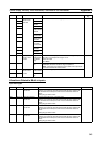
A571 00 Adjustment Mode
Status
Adjustment Opera-
tion Error
ON when an operational error has been made, such as
turning ON both the Analog Input and Analog Output 2
Adjustment Enable Bits at the same time.
Module
01 to 14 Reserved
15 Adjustment Mode
Started
ON during adjustment mode operation (when A575
contains 5A5A hex).
A572 00 to 15 Adjustment Mode
Monitor
(Effective only
when A575 is
5A5A hex.)
Both Analog Input
and Analog Out-
puts
Setting Off-
set Monitor
The values in
these words
can be over-
written
directly, with-
out using the
Adjustment
Value Incre-
ment/Decre-
ment Bits.
•
−10 to 10 V: FE0C to
01F4 hex
• 0 to 10 V, 0 to 5 V, 1 to
5 V: FF38 to 00C8 hex
Module/User
A573 00 to 15 Gain Value
Monitor
•
−10 to 10 V: 1194 to
157C hex
• 0 to 10 V, 0 to 5 V, 1 to
5 V: 0ED8 to 1068 hex
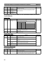
A574 00 to 15 Analog Inputs Number of
Average
Value Sam-
ples in Adjust-
ment Mode
Indicates the number of values to be
averaged to obtain the Offset/Gain
Value Monitor values in adjustment
mode. The number of samples can be
set between 0000 and 0040 hex (0 to
64). Set this parameter before turning
ON the Adjustment Enable Bit.
User
A575 00 to 15 Adjustment Mode Password 5A5A hex: Adjustment mode enabled.
Other value: Adjustment mode disabled.
User