


144
Input Interrupts Section 7-3
Counter Mode Procedure
1,2,3... 1. Determine which input interrupt number will be used.
2. Determine the initial SV for the decrementing counter.
3. Wire the input.
4. Make the necessary System Setup settings.
• Set the Interrupt Input Settings (set whether an interrupt will be generated
when the input turns ON, OFF, or both).
Note The default input setting is for a normal input.
5. Create the necessary ladder programming.
• Use the MSKS(690) instruction (SET INTERRUPT MASK) to refresh the
counter’s SV in counter mode.
• Create the interrupt task program.
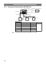
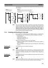
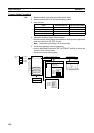
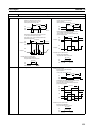
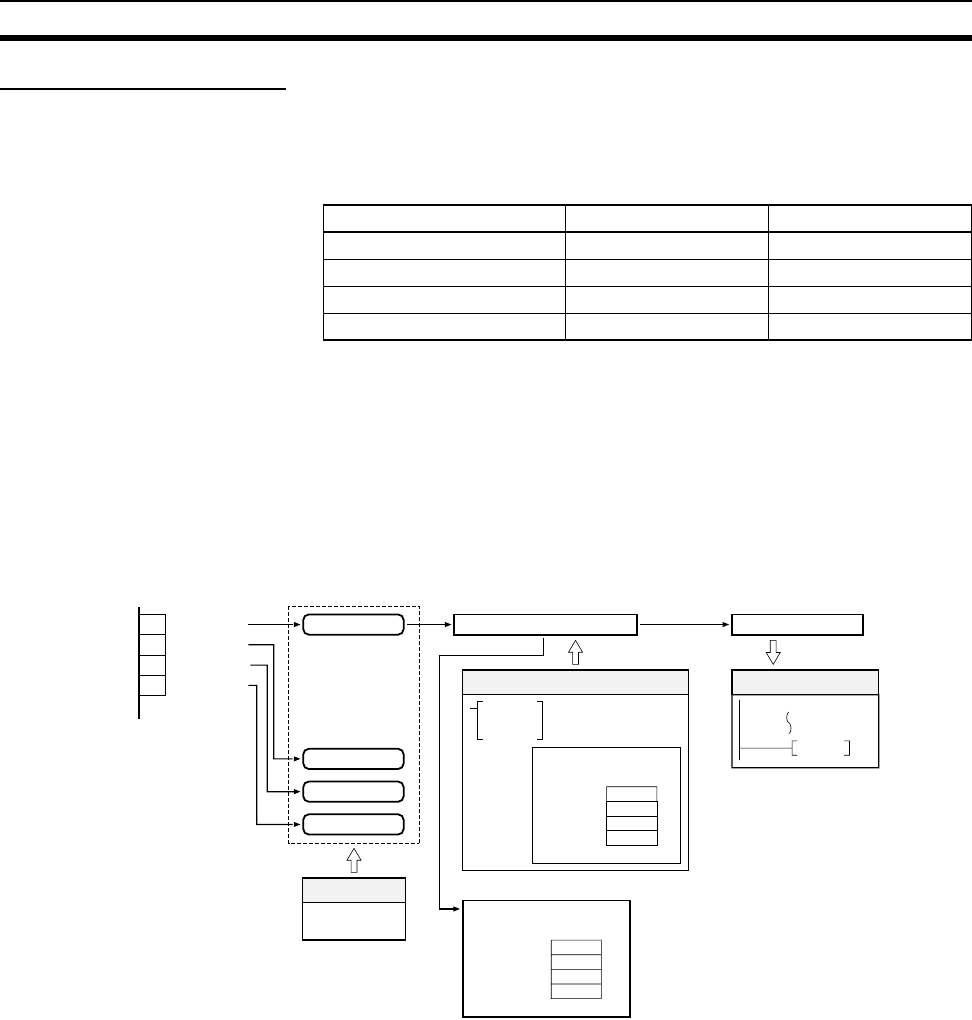
Input Allocated input bit Interrupt task number
External interrupt input 0 CIO 0000.00 000
External interrupt input 1 CIO 0000.01 001
External interrupt input 2 CIO 0000.02 002
External interrupt input 3 CIO 0000.03 003
0 CIO 0000.00
1
CIO 0000.01
2
CIO 0000.02
3
CIO 0000.03
MSKS
Change SV (Decrementing)
Counter SV
A520Counter 0
A521Counter 1
A522Counter 2
A523Counter 3
(Auxiliary Area)
Interrupt input (counter mode)
END
See note.
Note:
Refresh PV (once each cycle)
Counter PV
Interrupt
input
Counter 0, 1 kHz
Interrupt control
Refresh PV
(Decrementing)
Ladder program
Interrupt input
settings
System Setup
Interrupt generated.
Execute specified task.
Counter 1, 1 kHz
Counter 2, 1 kHz
Counter 3, 1 kHz
A524Counter 0
A525Counter 1
A526Counter 2
A527Counter 3
(Auxiliary Area)
Interrupt used only when
the counter counts out.