


57
Installation Section 3-1
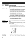
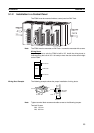
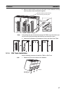
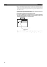
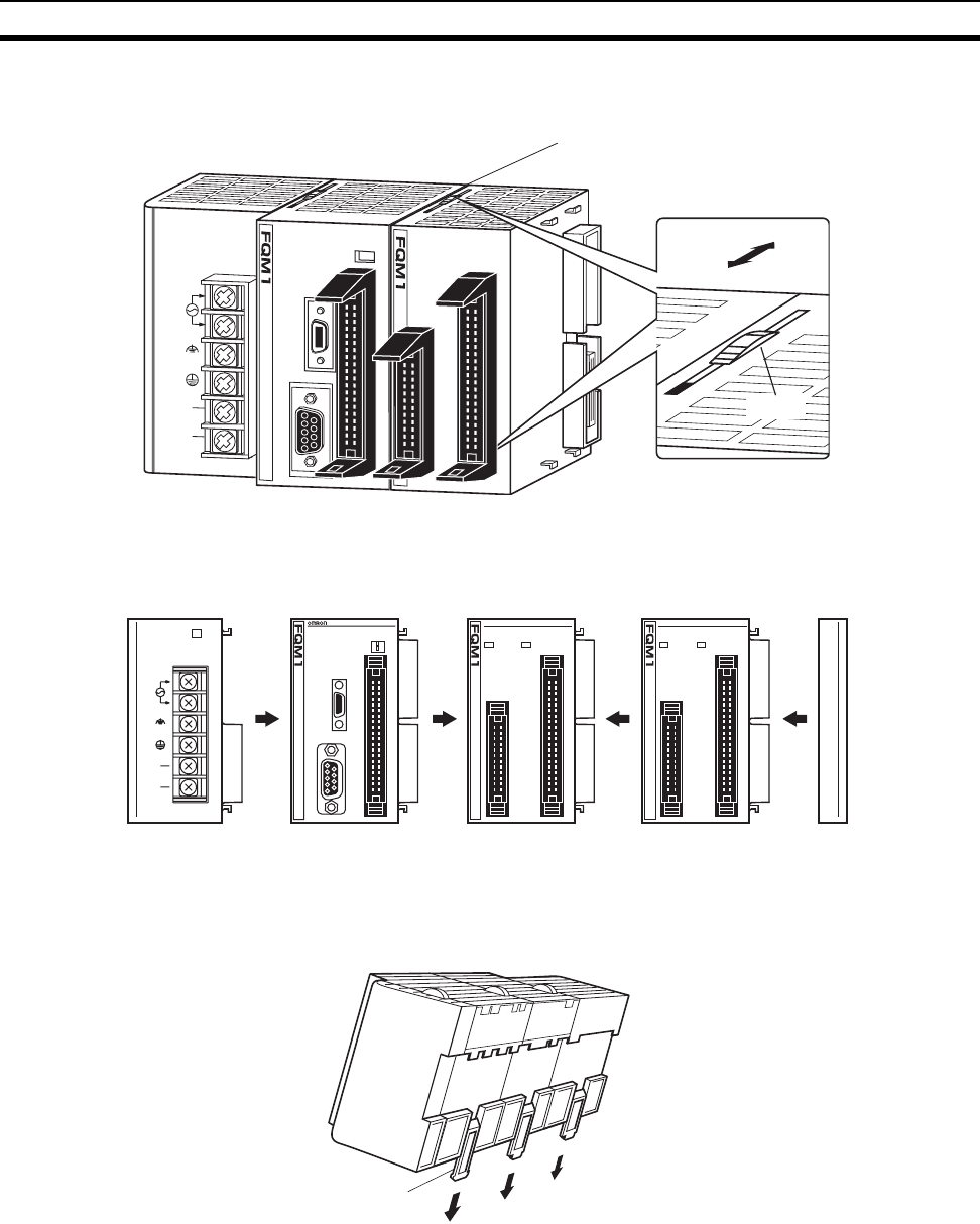
2. Move the yellow sliders at the top and bottom of each Module until they
click into place to lock the Modules together.
Note If the locking tabs are not secured properly, the FQM1 may not function prop-
erly. Be sure to slide the locking tabs until they are securely in place.
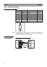
3. Attach the End Module to the Module on the far right side of the FQM1.
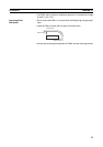
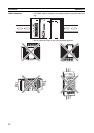
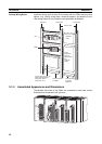
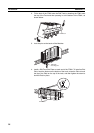
3-1-5 DIN Track Installation
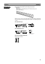
Use the following procedure to install the FQM1 on DIN Track.
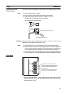
1,2,3... 1. Release the pins on the backs of the Modules.
Slide the sliders towards the back
cover until they click into place.
INPUT
AC100
-240V
L2/N
L1
NC
NC
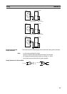
Lock
Unlock
Slider
FLEXIBLE
MOTION
CONTROLLER
RDY
RUN
ERR
PRPHL
COMM1
COMM2
PERIPHERAL
PORT
ON
OFF
CM001
2
CN1
RS422
1
4039
1 2
MMP21
2
CN2
CN1
1
12
4039
2526
IN OUT
0
1
2
3
4
5
6
7
8
9
10
11
0
1
2
3
4
5
6
7
RDY
RUN
ERR
A1
B1
A2
B2
MMA21
2
CN2
CN1
1
12
4039
2526
IN OUT
0
1
2
3
4
5
6
7
8
9
10
11
0
1
2
3
4
5
6
7
RDY
RUN
ERR
A1
B1
A2
B2
NC
NC
INPUT
AC100
-240V
L2/N
L1
PA202
POWER
Release
DIN Track
mounting pins