


271
Programming Appendix A
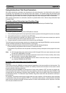
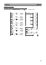
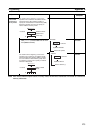
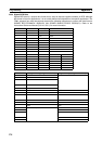
Instruction Location and Input Conditions
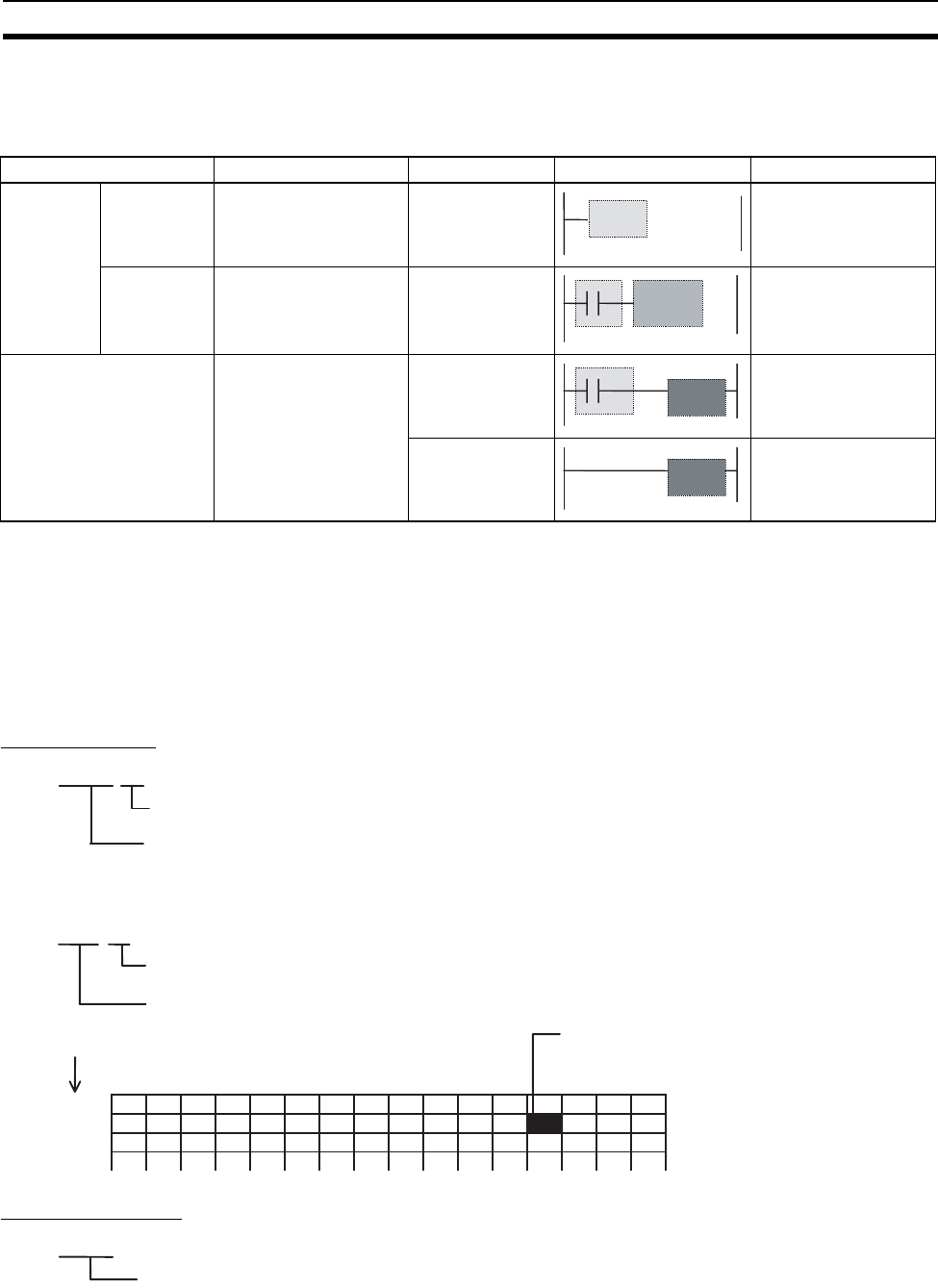
The following table shows the possible locations for instructions. Instructions are grouped into those that do
and those do not require input conditions.
Note (1) There is another group of instructions that executes a series of mnemonic instructions based on a
single input. These are called block programming instructions. Refer to the Instructions Reference
Manual (Cat. No. O011) for details on these block programs.
(2) If an instruction requiring an input condition is connected directly to the left bus bar without a logical
start instruction, a program error will occur when checking the program on the CX-Programmer.
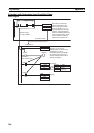
Addressing I/O Memory Areas
Bit Addresses
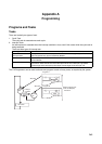
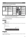
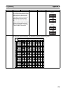
Example: The address of bit 03 in word 0001 in the CIO Area would be as shown below. This address is given
as “CIO 0001.03” in this manual.
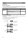
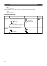
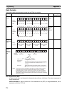
Word Addresses
Example: The address of bits 00 to 15 in word 0010 in the CIO Area would be as shown below. This address
is given as “CIO 0010” in this manual.
Instruction type Possible location Input condition Diagram Examples
Input
instructions
Logical start
(Load
instructions)
Connected directly to
the left bus bar or is at
the beginning of an
instruction block.
Not required. LD, LD >, and other
symbol comparison
instructions
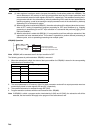
Intermediate
instructions
Between a logical start
and the output instruc-
tion.
Required. AND, OR, AND >, and
other symbol compari-
son instructions)
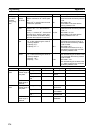
Output instructions Connected directly to
the right bus bar.
Required. Most instructions
including OUT and
MOV(021).
Not required. END(001), JME(005),
ILC(003), etc.
@@@@.@@
Bit number (00 to 15)
Word address
0001. 03
Bit number (03)
Word address: 0001
15 14 13 12 11 10 09 08 07 06 05 04 03 02 01 00
0000
0001
0002
Word
Bit: CIO 0001.03
@@@@
Word address