


89
Wiring Precautions Section 3-6
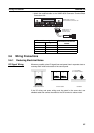
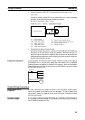
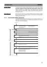
3. Relation between FQM1 OFF current and sensor leakage current:
I
OFF
≥ I
leak
Connect a bleeder resistor R if I
leak
is greater than I
OFF
. Use the following
equation to calculate the bleeder resistance constant.
R
≤ (R
IN
× V
OFF
)/(I
leak
× R
IN
– V
OFF
)
Power W
≥ (V
CC
– V
R
)
2
/R × 4 [allowable margin]
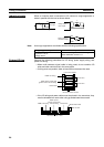
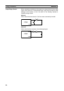
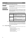
4. Precautions on Sensor Surge Current
An incorrect input may occur if a sensor is turned ON after the FQM1 has
started up to the point where inputs are possible. Determine the time re-
quired for sensor operation to stabilize after the sensor is turned ON and
take appropriate measures, such as inserting into the program a timer de-
lay after turning ON the sensor.
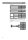
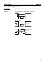
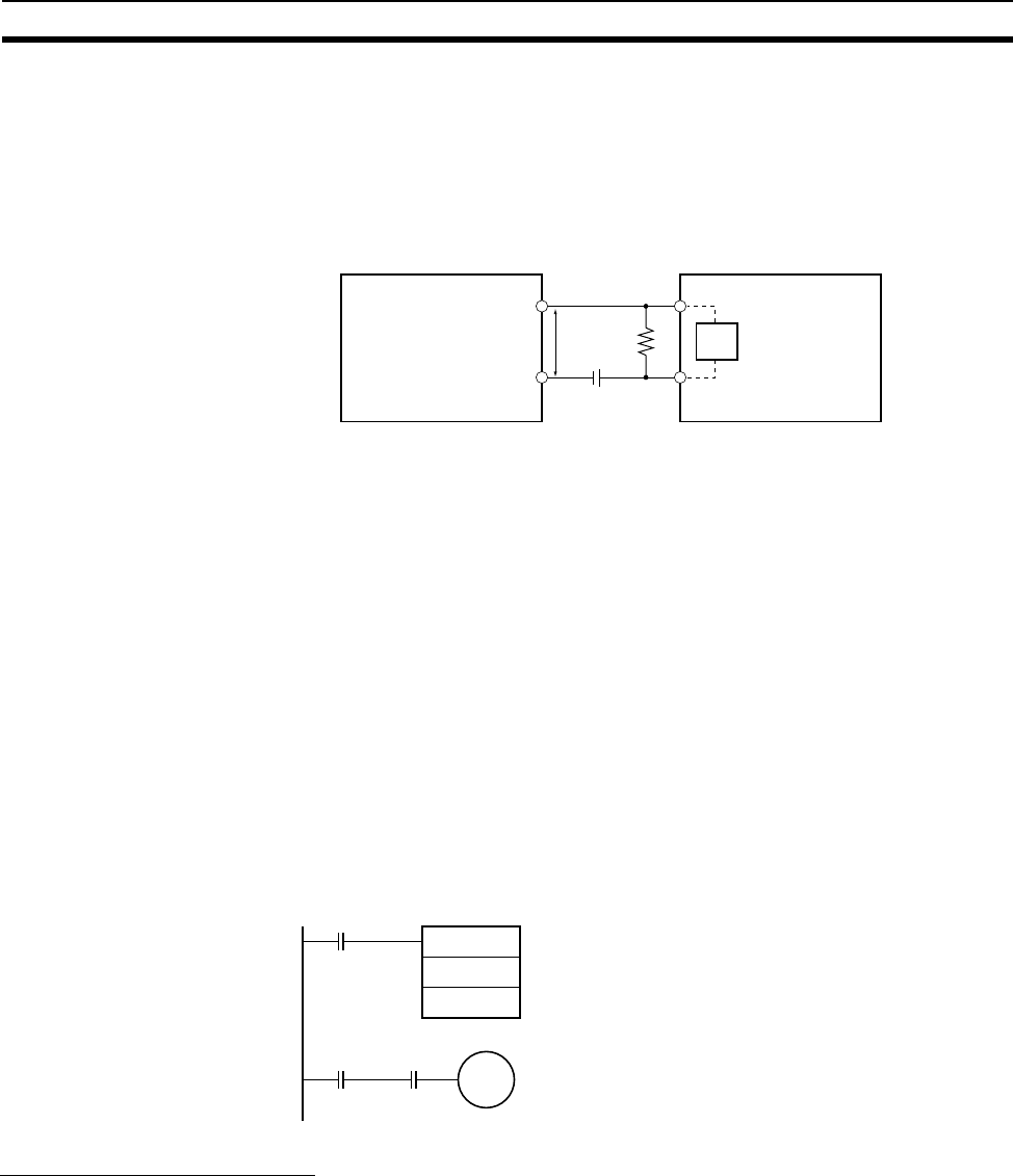
Programming Example In this example, the sensor’s power supply voltage is used as the input to
CIO 0000.00 and a 100-ms timer delay (the time required for an OMRON
Proximity Sensor to stabilize) is created in the program. After the Completion
Flag for the timer turns ON, the sensor input on CIO 0000.01 will cause output
bit CIO 0001.00 to turn ON.
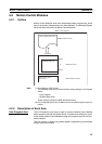
Output Wiring Precautions
Output Short-circuit
Protection
If a load connected to the output terminals is short-circuited, output compo-
nents and printed circuit boards may be damaged. To guard against this,
incorporate a fuse in the external circuit. Use a fuse with a capacity of about
twice the rated output.
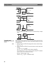
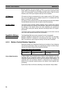
Transistor Output
Residual Voltage
A TTL circuit cannot be connected directly to a transistor output because of
the transistor’s residual voltage. It is necessary to connect a pull-up resistor
and a CMOS IC between the two.
RVR
VCC
RIN
V
CC
:
V
ON
:
V
OFF
:
I
ON
:
I
OFF
:
R
IN
:
V
R
:
I
OUT
:
I
leak
:
R:
Sensor output residual voltage
Sensor control current (load current)
Sensor leakage current
Bleeder resistance
Power voltage
FQM1 ON voltage
FQM1 OFF voltage
FQM1 ON current
FQM1 OFF current
FQM1 input impedance
Two-wire sensor
DC input
TIM
0000
#0001
0000.00
TIM0000 0000.01
0001.00