


95
Motion Control Modules Section 4-2
4-2 Motion Control Modules
4-2-1 Outline
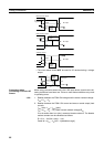
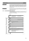
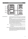
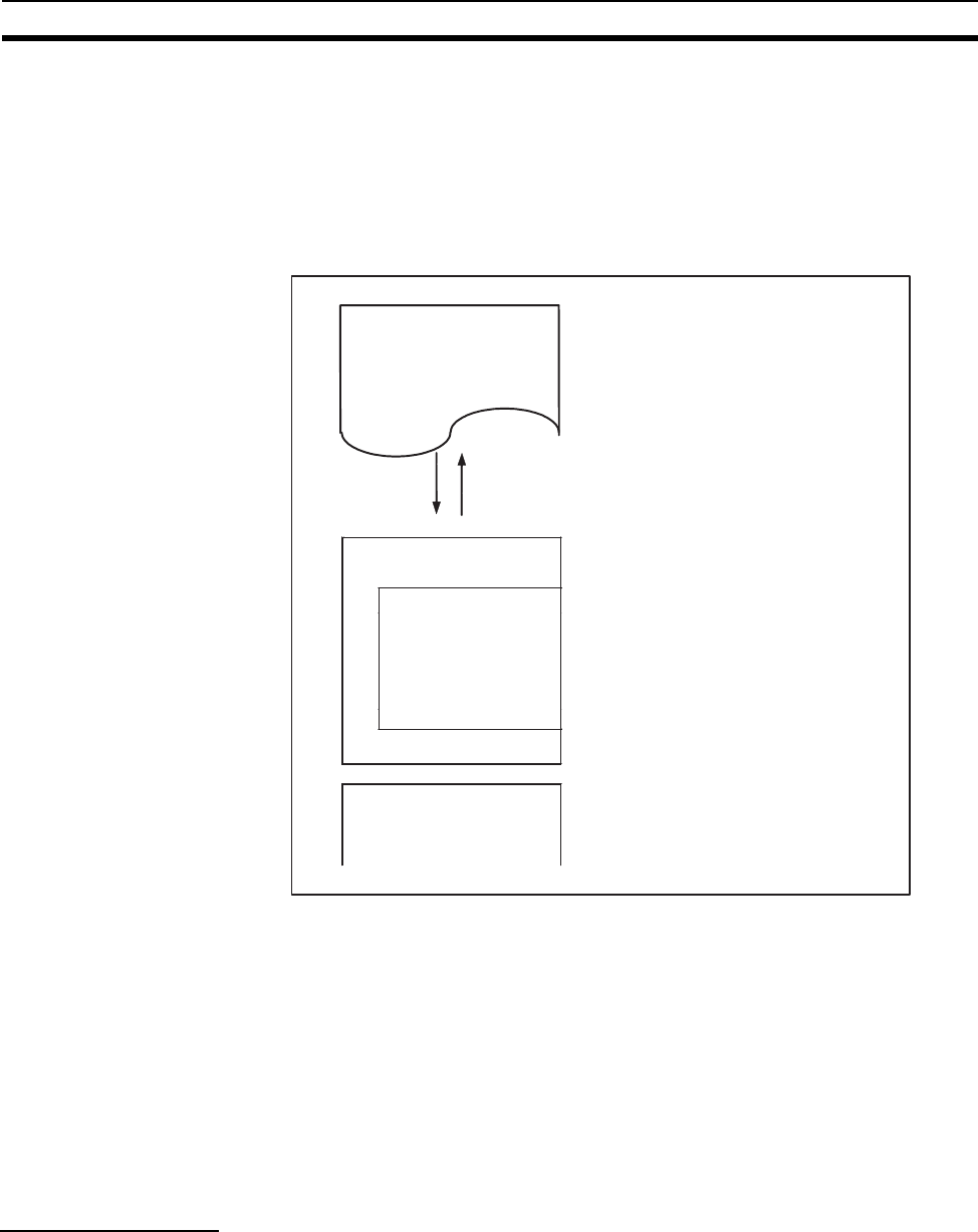
Motion Control Modules each have independent ladder programming, which
perform processing independently from other Modules. The following diagram
shows the internal structure of Motion Control Modules.
Note (1) User Memory (UM) Protect
The following data can be write-protected using settings in the System
Setup.
• User program
• System Setup Area
These Areas are stored in RAM and flash memory.
(2) Part of the DM Area in the I/O Memory Area is backed up by a super ca-
pacitor.
4-2-2 Description of Each Area
User Program Area The CX-Programmer (see note) is used to create the Motion Control Module
ladder programs and set the System Setup. Programs and settings are trans-
ferred to each Motion Control Module through the peripheral port on the Coor-
dinator Module.
The user program is written using ladder diagram programming and executed
using a cyclic scan method.
D00000
D32767
to RAM (See note 2.)
Motion Control Module
User program (See note 1.)
RAM and flash memory
I/O memory
General-purpose
Read/Write DM Area
System Setup Area
(See note 1.)
RAM and flash memory