


321
System Setup, Auxiliary Area Allocations, and Built-in I/O Allocations Appendix C
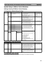
System Setup in Motion Control Modules
Settings Used by All Motion Control Modules
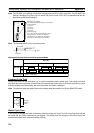
CX-Programmer: Module Settings Tab Page
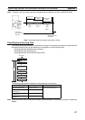
CX-Programmer: Cycle Time Tab Page
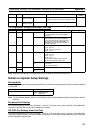
CX-Programmer: Other Tab Page
These settings are reserved for future expansion of Motion Control Module functionality.
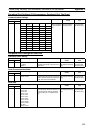
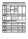
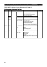
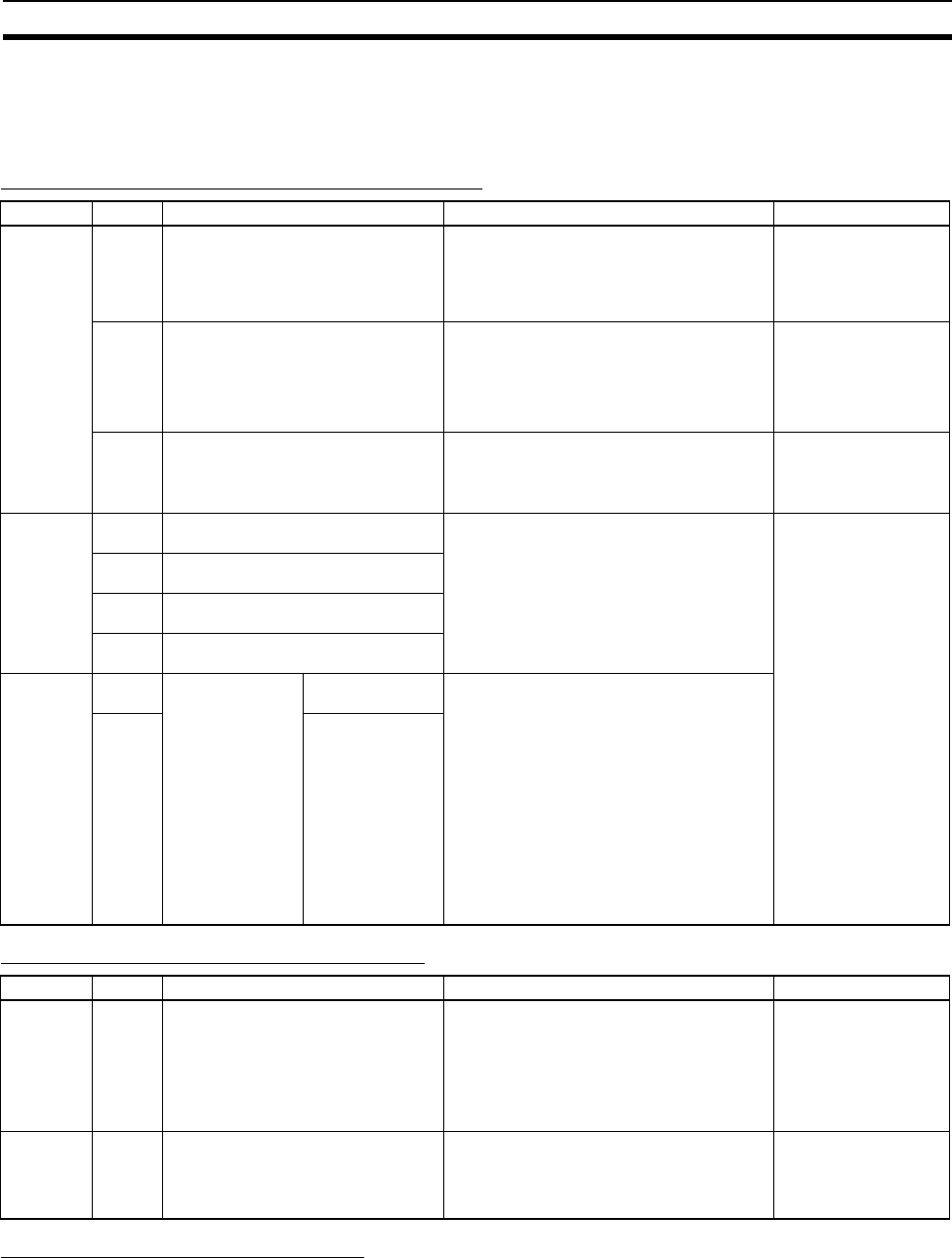
Address Bits Function Remarks When setting is read
+304 00 Allow writing to user memory (user
memory protection)
0 hex: Writing enabled
1 hex: Writing disabled
Note Set this bit to 1 to disable writing the fol-
lowing areas from the CX-Programmer: user
program and System Setup
When disabling: At
power ON or at start of
operation
When enabling: When
changed
08 Prohibit system interruption of the sync
mode
0 hex: Allow interrupts
1 hex: Prohibit interrupts
Set this bit to 1 to prohibit system interrupts
during program execution and I/O memory
refreshing to maintain synced operation
between Modules in Sync Mode.
At power ON
12 Detect cycle time over warming (detec-
tion of cycle times longer than 10 ms)
0 hex: Detect long cycles
1 hex: Do not detect long cycles
Note CIO 0105.09 will turn ON if this bit is set
to 0 and the cycle time exceeds 10 ms.
At start of operation
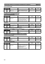
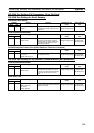
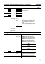
+305 00 to 03 Interrupt Input Settings, Input 0 (CIO
0000.00) function
0 hex: Normal
1 hex: Interrupt input (at rising edge)
2 hex: Interrupt input (at falling edge)
3 hex: Interrupt input (at both edges)
Note Interrupt input settings of 1 to 3 hex
apply to input interrupt mode and counter
mode.
At power ON
04 to 07 Interrupt Input Settings, Input 1 (CIO
0000.01) function
08 to 11 Interrupt Input Settings, Input 2 (CIO
0000.02) function
12 to 15 Interrupt Input Settings, Input 3 (CIO
0000.03) function
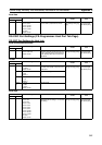
+306 00 to 07 Select Synchro-
nous Data
Upper 2 words (+0
and +1)
00 hex: Normal (via Ladder)
01 hex: High-speed counter PV (Counter 1 val-
ues)
02 hex: High-speed counter PV (Counter 2 val-
ues)
03 hex: Pulse output 1 PV
04 hex: Pulse output 2 PV
05 hex: Analog input
06 hex: Reserved
07 hex: Analog output 1 value
08 hex: Analog output 2 value
09 hex: Built-in input value (Inner I/O input)
5A hex: No data
08 to 15 Lower 2 words (+2
and +3)
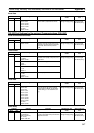
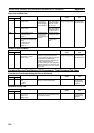
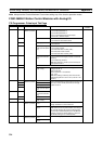
Address Bits Function Remarks When setting is read
+307 00 to 15 Cycle time 0000 hex: Variable cycle time
0001 to 03E8 hex: Constant (minimum) cycle
time of 0.1 to 100.0 ms (unit: 0.1 ms)
If the actual cycle time is less than this setting,
it will be extended until this time passes.
Note A404.05 will turn ON if the minimum
cycle time set here is exceeded.
At start of operation
+308 00 to 15 Watch cycle time Change this setting only when you want to
change the default maximum cycle time. The
Cycle Time Too Long Flag (A401.08) will be
turned ON if the actual cycle time exceeds this
setting.
At start of operation