


164
Pulse Inputs Section 7-5
Example 2:
High-speed Counter
Range Comparison &
Bit Pattern Output
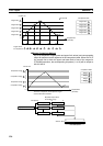
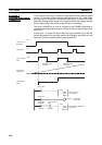
In this example, pulse input 1 operates a high-speed counter, the high-speed
counter PV is compared in a range comparison, and corresponding bit pattern
is output internally when the PV is within a specified range. The internal bit
pattern value is output by a transfer to CIO 0001.
The Reset Bit is kept ON in the program and the counter PV is reset when the
phase-Z signal turns ON after the PV reaches its maximum value. Before run-
ning the program, make the following settings in the System Setup and restart
the FQM1 to enable the new settings.
Counter 1:
Linear counter, Counting speed = 50 kHz, Phase Z and software reset, and
Increment/decrement pulse input
The other System Setup settings are left at their default settings.
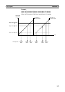
Example
When the PV is between 0 and 2,500 hex, CIO 0001.00 is ON.
When the PV is between 2,501 and 7,500 hex, CIO 0001.01 is ON.
When the PV is between 7,501 and 10,000 hex, CIO 0001.02 is ON.
When the PV is 10,001 hex or higher, CIO 0001.03 is ON.
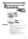
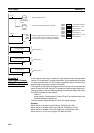
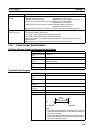
@CTBL
#0001
#0000
D00000
Registers a target value comparison table for the PV
from high-speed counter 1 and starts the comparison.
(In this case, the comparison table begins at D00000.)
D00000 0 0 0 3
D00001 2 5 0 0
D00002 0 0 0 0
D00003 0 0 0 A
D00004 7 5 0 0
D00005 0 0 0 0
D00006 0 0 0 B
D00007 0 0 0 0
D00008 0 0 0 1
D00009 0 0 0 C
A610.00
Turns ON the High-speed Counter 1 Reset Bit.
P_On
(Always ON)
Reset Bit
A610.01
Starts high-speed counter 1.
Start high-speed
counter.
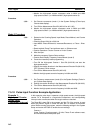
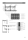
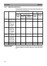
0002.00
Interrupt task 10
Control program 1
Interrupt task 11
Interrupt task 12
Control program 2
Control program 3
3 comparison conditions
Target value 1 = 2,500
Interrupt task 10
Target value 2 = 7,500
Target value 3 = 10,000
Interrupt task 11
Interrupt task 12
END
END
END
END