


WEBVISION™
93 95-7769—01
Purpose
To configure setpoint values for the XL15C.
Mode
Configuration can be performed with the wizard Off-line or
On-line.
Procedure
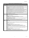
1. On the Configuration page click SetPoints [Loop
Logic]. The Set Point page appears on the right pane.
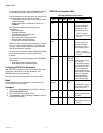
2. Type a Float Value. There are 40 setpoints. Enter the
value of the setpoint in this field. The setpoint has a
default value of 0 by default. The valid ranges for a
setpoint are -99999 to +99999 with 5 digits maximum
and a resolution of 0.0001.
3. Select Engineering Units. This list contains
engineering units that may be assigned to the setpoint.
Select the desired engineering unit from the list.
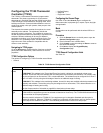
Configuring XL15C Math Functions
You can configure a maximum of 30 math functions. Math
functions are of two types: General Purpose and Network
Special. The General Purpose math function operates on a
maximum of six floating point analog inputs. These Inputs can
be a physical or remote point value, set point, output of a flex,
logic loop, or a math function. You can in turn specify the math
functions output to be used by any flexible, logic loop, or a
math function.
A minimum of two analog inputs need to be selected if you are
configuring a Network Special math function.
Purpose
General Purpose Math functions are used to perform
operations like minimum, average, square root etc. on up to 6
floating point analog values available within the controller.
Mode
Configuration can be performed with the wizard Off-line or
On-line.
Procedure
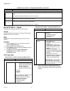
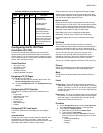
1. On the Configuration page click Math Functions. The
Math Function page appears on the right pane.
2. Select a required math function from Select Function.
3. Type a Function Name.
4. Select an operator from Select Operator.
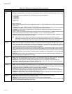
Configuring XL15C Control Loops
The XL15C controller may be configured for up to 10 Control
Loops.
In the simplest form, a Control Loop reads a sensor (i.e. the
control sensor) and calculates an output to maintain the
sensed value at a user defined set-point. There are many
variations of this. For inputs, the user can configure control,
reset, recovery, occupancy, enable/disable, and TOD bypass
sensors. For outputs, the users may configure up to 4
modulating analog outputs, up to 4 stages for each analog
output and an auxiliary digital output for controlling a fan or
pump.
The control portion of the loop is an Enhanced PID (EPID)
algorithm. The user configures control algorithm type (PID or
Non-linear), bias (position of set point within the proportional
band (i.e. 0% or 50%), direct/reverse acting output, which
sensor and outputs to use, throttling range, integral time,
derivative time, start up ramp time, recovery, reset and
sequencer parameters, set points, minimum on, off and
bypass times, DLC shed bump and lead/lag.
Purpose
Define up to ten control loops that create outputs based on
algorithms.
Mode
Configuration can be performed with the wizard Off-line or
On-line.
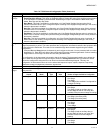
Procedure
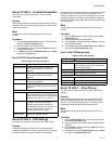
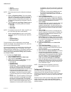
1. On the Configuration page click Control Loop. The
Control Loop page appears on the right pane.
2. Select a control loop from Select Loop.
3. Type a Loop Name.
4. Select Algorithm Type. This field defines the algorithm
type for the control loop. The default type is
“Unconfigured”. The user can select the type to be “Flex
PID” or “Flex Non-Linear”. Only if the algorithm type is
“Flex PID” or “Flex Non-Linear” will the other controls in
the Control Loop page get enabled. Select the
corresponding radio button to select an algorithm type.
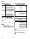
5. Select a priority from Occupancy Override Priority.
The two options for occupancy override priority are:
•With Network wins (the default), nviManOcc has
priority. If nviManOcc is some other value than
OC_NUL, then the result is the value on
nviManOcc. When nviManOcc is OC_NUL, then
nviBypass has priority. If nviBypass is SW_OFF/
SW_NUL then the wall module override is
evaluated. Both nviManOcc and the wall module
override use the internal bypass timers. nviBypass
depends upon the other node’s timer to control the
duration of the bypass. The Excel 15C keeps the
loop bypass_timer running while nviBypass is
SW_ON. If nviBypass goes away before the timer
expires, then the loop remains in bypass for the
balance of the timer.
•With Last in Wins, the last bypass source is used to
determine the state. If multiple sources change the
state in the same second, they are evaluated in
order: nviManOcc, nviBypass, wall module override.
Each second the algorithm looks for an update to
either nviManOcc, a change of state to nviBypass,
or the wall module override being pushed. If any of
these occur, then appropriate action is taken. Else,
the bypass timer is checked for expiration and the
current state returned.
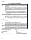
6. Select/Type information for the following.
a. Input & Setpoints
• Inputs: Used to configure the inputs required for
the Control Loop.
• Setpoints: Control Loop can host separate
setpoints apart from main 40 setpoints. These
are used to drive the occupancy state of the
control loop.