


WEBVISION™
63 95-7769—01
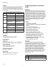
FCU PID
Purpose
Configure the variables for closed loop control. PID
parameters can be set separately for both heating and cooling
control.
Mode
Configuration can be performed with the wizard Off-line or
On-line.
Procedure
1. Click the PID button on the left pane to open the PID
Configuration page.
2. Enter information into available fields.
3. Click Commit to save the settings or Reset to revert to
the last saved settings.
4. Click Next to display the Wiring Diagram
Configuration page or Back to display the
Miscellaneous Configuration page.
FCU PID fields
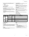
FCU Wiring Diagram
Purpose
Display the wiring diagram for the controller.
Mode
Configuration can be performed with the wizard Off-line or
On-line.
Procedure
1. Click the Wiring button on the left pane to open the
Wiring Configuration page.
2. Enter information into available fields.
3. Click Commit to save the settings or Reset to revert to
the last saved settings.
4. Click Back to display the PID Configuration page.
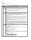
FCU Wiring Terminals
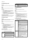
DI1 Window / Occupancy / Air Flow / Changeover.
Energy
Management
(continued)
Cool.Rec.Ramp, Heat.Rec.Ramp
Define the rate at which the setpoint is reset
during changes between occupancy modes
to provide a form of optimum start algorithm.
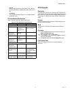
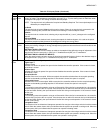
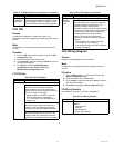
Table 38. FCU PID Options.
Name Definitions
PID Cooling/Heating
Proportional band
This value is the temperature deviation
between setpoint and space temperature,
which causes the control output to modulate
from 0% to 100% of full range.
• Range 2 DDC to 100 DDC (3.6 to 180
DDF) for PID control, respectively;
1.3. to 100 DDC (2.3 to 180 DDF) for P
Control only.
Reset Time
This value is the integral reset time in the
range 0 to 3200 sec. Setting the Integral
constant to zero disables integral operation.
Derivative Time
This value is the derivative constant in the
range 0 to 3200 sec. Setting the derivative
constant to zero disables derivative operation.
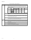
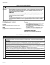
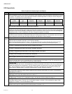
Table 37. FCU Miscellaneous Field Options. (Continued)
Name Definitions
Thermal
Switching
Band/PID
Boost
Cooling /Heating
Boost Temp
Sets a boost band for normal PID operation
and when using thermal actuators. The
variables indicate a setpoint-space
temperature deviation outside, which switches
the outputs to full operation This option acts as
a boost function when space temperature
deviates significantly from the desired
setpoint. This option also serves as a
threshold for two-point switching of thermal
actuators.
• The threshold can be set in the range
0 to 10 DDC (7.2 to 180 DDF).
• If the threshold is set to 0 DDC, the boost
function is disabled.
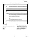
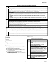
Table 39. FCU Wiring Diagram.
Name Definitions
Wall Module Use these terminals to connect the Wall
Module:
• Override LED
• Setpoint
• Bypass Button
• Room Temp Sensor
Table 38. FCU PID Options. (Continued)
Name Definitions