


WEBVISION™
95-7769—01 22
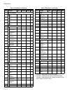
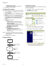
Load Shedding Method
1. The DLC starts shedding by first searching for all the Off
Continuous loads that are eligible for shedding.
2. Then, it first sheds the lowest numbered Off Continuous
load and waits the staging interval to see if the demand
has reduced.
3. If the demand is still above the peak setpoint, then DLC
sheds another Off Continuous load. This process
continues until the demand is well within the peak
setpoint limits.
4. If the demand has still not reduced, then DLC searches
for all the Rotated loads.
Load Restoring Method
• If the demand drops below the normal level, then the loads
that are currently shed will be actively restored one at a
time, every staging interval, until the demand reaches the
normal level. When restoring loads, DLC, on priority,
searches and restores:
• The Rotating loads where the load that has been shed
for the longest period is restored first.
• Then the Off Continuous loads where the load
restoration goes from highest load number to the
lowest load number.
• Loads are restored every staging interval if the override
condition becomes true or the maximum shed time has
been met. All loads that satisfy these conditions are
restored.
DLC Status
Demand Limit Control is a function that controls the maximum
power demand made on the whole system by shedding some
of the load based on priority where total power usage of
configured loads exceeds the predefined limit. Shedding
requires turning off some digital output, or changing a setpoint
to a more economical level.
You can view the DLC service status that includes all load
assignment details. DLC status is updated at the rate of the
staging interval.
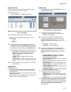
To view the status of the DLC:
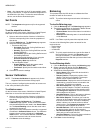
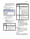
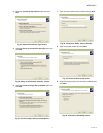
1. Click the DLC tab. The DLC Status page appears.
Fig. 27. DLC Status page.
2. The following information is displayed as read only text:
• Setpoint: Displays the setpoint value.
• Current KW: Displays the average power
consumption of the total assigned load.
• DLC Status: Displays the current DLC status. Four
modes present are: Disable, Deadband, Shed, and
Restore.
NOTE: Use Filters to quickly search the required DLC mode.
Use one of the following filter options to search for the
required load assignment:
• Load Name Pattern
• Shed Method
• Shed State
NOTE: To quickly search, type the first letter of the required
filter criteria in the Keyword text box and type an
asterisk (*). This lists all the names starting with the
first letter that you have written in the Keyword text
box.
3. The following information is displayed:
• Load Assignment Name
• Min On/Shed Time
• Max Shed Time
• Shed Status
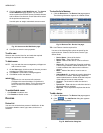
To configure the DLC:
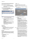
1. Click the DLC tab. The DLC Status page appears.
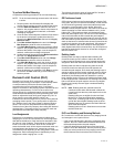
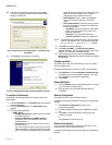
2. Click the Configure tab. The Configure page appears.
Fig. 28. DLC Configure page.
3. Select the pulse meter options. Click Select Point. A
Selected Pulse Meter pop up appears. Select a
Channel, Device, and Point for configuring DLC and
click OK.
NOTE: Check the Disable DLC Service check box to
disable the DLC service.
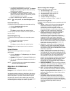
4. Enter/Select the following parameters:
• Peak Set Point: Enter the setpoint to set as the
peak limit. The range for peak set point value is 0-
6000.
• Demand Window Period: Select the demand
window period from the Demand Window Period
drop-down list. The valid range is in steps of 1
minute to 15 minutes. It is the time interval over
which the instantaneous KW demand is averaged to
determine the effective KW peak demand value.
This value, in turn drives the DLC to shed or restore
loads. The demand value is read from the pulse
meter for every 15 seconds and the average
demand value is calculated accordingly.
• Staging Interval: Select the staging interval from
the Staging Interval drop-down list. The valid range
is in steps of 20 seconds to 120 seconds.
WebVision collects the KW samples for every 15