


WEBVISION™
95-7769—01 48
CVAHU Equipment Control
Description
Sensor type, Cascade control options, COR Mode, Fan, and
Smoke control options.
Purpose
Define equipment control settings.
Mode
Configuration can be performed with the wizard Off-line or
On-line.
Procedure
1. Click the Equipment Control button on the left pane to
open the Equipment Control Configuration page.
2. Enter information into available fields.
3. Click Commit to save the settings or Reset to revert to
the last saved settings.
4. Click Next to display the Economizer Parameters
Configuration page or Back to display the Input
Configuration page.
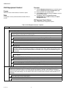
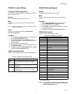
CVAHU Equipment Control fields
Table 21 lists the CVAHU Equipment Control fields.
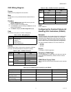
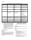
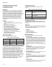
Table 20. Use Wall Module vs. Override Priority.
Sensor
Use Wall
Module as
Setpoint in
Zone Option
page
Use Override
Priority
in
Miscellaneous
Parameter
page Meaning
Sensor
only
No None Use Wall Module
as Sensor only
Sensor
Setpoint
Yes None Use Wall module
as Sensor as well
as get set point.
Sensor
Bypass
No Normal
Bypass
Use Wall module
as Sensor as well
as for bypass.
Sensor
Setpoint
Bypass
Yes Normal
Bypass
Use the Wall
module as the
Sensor source for
temperature
setpoint as well
as input to bypass
scheduled
occupancy state
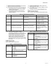
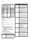
Table 21. CVAHU Equipment Control Fields.
Name Definition
Main Sensor Set sensor type, if any, to Space
Temperature or Return Air Temperature.
Return Air option is available only if a
Return Air sensor is configured on the
CVAHU Controller Inputs page.
Cascade Control Configure cascade control. Default is No.
Yes is available only if both a Discharge
Air Temperature sensor and modulating
heating or cooling are configured.
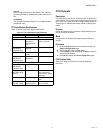
C.O.R. Fail Mode Changeover Relay (For Heat Pump only)
fail mode: Heating or Cooling.
This option determines which mode
(Heating or Cooling) is activated on
power failure to the C.O.R. This item is
available only if HeatPump was selected
on the Output page.
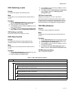
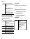
Fan Control You can select one of the following fan
control options:
• Auto - Auto cycles the fan with call for
cooling (and heating if Fan Heating is
On).
• Continuous - Indicates that the fan
runs continuously in the Occupied
mode, and intermittently (with call for
heating/cooling) in the Unoccupied
mode.
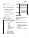
Fan-Heating Select one of the following options:
• On
• Off - Select Off to allow for control
circuits where, when in heat mode, the
fan is directly controlled by an
interlock control circuit (not part of the
Excel 10 controller) which brings on
the fan once the plenum temperature
has risen above its setpoint. This
option is typically used in roof top air
handlers with gas-fired heating.
Smoke Control This value determines what the controller
does when a smoke alarm occurs (either
from the digital input, or via the
L
ONWORKS network). Select one of the
following options:
• FanOffDmperClose
• FanOnDmperOpen
• FanOnDmperClosed
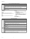
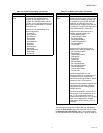
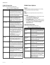
Fan Fail Time Enabled when Air Flow switch is
selected.
This value sets the amount of time that
must pass after fan start-up before the Air
Flow Switch is checked. This action
allows the fan to come up to speed and
prevents false air flow failure alarms.
Filter Pressure
Stpt
Filter Pressure Setpoint. Enabled if
analog Filter Pressure sensor is selected.
If the measured pressure exceeds this
setpoint, the Dirty Filter alarm is issued.
There is a built-in hysteresis of 25
percent of the Filter Press Stpt value (for
the Dirty Filter alarm to return to normal).
Table 21. CVAHU Equipment Control Fields. (Continued)
Name Definition