


WEBVISION™
53 95-7769—01
CVAHU Custom Wiring
Configuring CVAHU Custom Wiring
Use the CVAHU Custom Wiring page to assign configured
outputs to physical pins.
Purpose
View or modify sensor output wiring locations.
Mode
Configuration can be performed with the wizard Off-line or
On-line.
NOTE: To add or delete outputs, refer to “CVAHU Controller
Outputs” on page 45.
Limits
Outputs must be configured using the Unit Ventilator
Controller Outputs page.
Procedure
1. Click the Wiring Assignment button on the left pane to
open the Wiring Assignment page.
2. For Custom Assignment, select Custom from the
Output Assignment field. The Custom Assignment fields
become editable.
3. Enter information into available fields.
4. Click Commit to save the settings or Reset to revert to
the last saved settings.
5. Click Next to display the Wiring Diagram page or Back
to display the PID Configuration page.
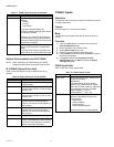
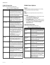
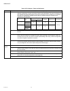
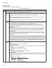
CVAHU Custom Wiring fields
Table 27 lists the CVAHU Custom Wiring fields and definitions.
CVAHU Wiring Diagram
Purpose
Display the wiring diagram for the controller.
Mode
Configuration can be performed with the wizard Off-line or
On-line.
Procedure
1. Click the Wiring Diagram button on the left pane to
open the Wiring Diagram Configuration page.
2. Enter information into available fields.
3. Click Commit to save the settings or Reset to revert to
the last saved settings.
4. Click Back to display the PID Configuration page.
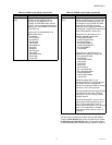
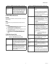
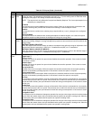
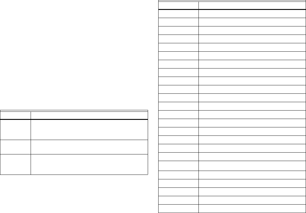
CVAHU Wiring Terminals
Table 28 lists the CVAHU Wiring terminals.
NOTE: Fields appearing grayed out indicate those fields that
change based on the Controller Type selected on the
Outputs Configuration page.
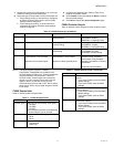
Table 27. CVAHU Custom Wiring Fields.
Name Definition
Default
Assignment
This column displays the default assignments
as the outputs are configured in the Outputs
page.
Custom
Assignment
Custom assignment is used to change the
assignments.
Existing If the device is online, this shows the
assignments as in the device. Else, it shows
from the database.
Table 28. CVAHU Wiring Terminals.
Terminal Connected To
1 Earth Ground
2LED
3 Bypass
4Sensor
5 AI Ground
6Set Point
7 AI-1 Ohm
8 AI Ground
9DI-1
10 and 11 DI Ground
12 DI-2
13 Not used
14 and 15 L
ONWORKS Bus
16 through 20 Not used
21 Vac Com
22 Vac
23 Rh
24 Rc
25 and 26
Network (DO1)
a
a
DO = Digital Output
27 G (DO2)
28 Y2 (DO3)
29 W2 (DO4)
30 W1 (DO5)
31 Not used (DO6)