


WEBVISION™
95-7769—01 58
FCU Inputs fields
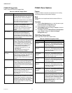
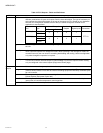
Table 33 lists the FCU Inputs fields and definitions.
Table 33. FCU Inputs Fields.
Name Definition
Wall
Module
Configures the functionality of the connected wall module. Always ensure that the features configured here are the
same as the features available on the wall module device to be connected.
Space
Temp
Sensor
Specify whether or not the controller is to be used with a space temperature sensor connected to its input. A
space temperature sensor is typically used, but in cases where the space temperature is supplied from
another device via the network, the local space temperature sensor input is not used.
YES
The local space temperature sensor input is used. Ensure that a space temperature sensor is actually
connected otherwise the controller measures incorrect values.
NO
The local space temperature sensor is not used. This option must be selected when a sensor is not
connected.
LED/LCD
Display
This configuration defines whether a Wall Module with LED or a Wall Module with LCD Display is connected.
For the LED there is shown either the Override Status or the Effective Occupancy Status. The LCD Display
show both the Effective and the Override Status, and an additional Off Condition.
The Override Status results from the Scheduler, the Network Override, the Override Button and the
Occupancy Sensor. The Off Condition results from the Fanspeed Switch, the Window Contact and the
Medium from nviApplicMode.
LED Override
The LED shows the Override from the Override Button or from the Network. On indicates Override Bypass, 1
Flash per Second indicates Override Unoccupied, 2 Flashes per Second indicates Override Standby or
Occupied. 4 Flashes indicates the Controller answers of the Network Management Command Wink.
LED Occupancy
The LED shows the effective Occupancy Mode. On indicates effective Occupied or Bypass, 1 Flash per
Second indicates effective Standby, Off indicates effective Unoccupied. 4 Flashes indicates the Controller
answers of the Network Management Command Wink.
LCD Display
This mode is used only for a Wall Module with LCD Display. The Display has following Symbols to show the
Occupancy Modes: Sun indicates effective Occupied or Bypass, Half Sun indicates effective Standby, Moon
indicates effective Unoccupied. No Symbol and OFF in 7-Segment indicates the Controller is Off. In the Off
Mode, a Snow Flag indicates whether Frost Protection is configured. Blinking Symbols are used to show the
Override: Blinking Sun indicates Override Occupied or Bypass, blinking Half Sun indicates Override Standby,
Blinking Moon indicates override unoccupied. The Controller answers with the Network Management
Command Wink with blinking Sun and Moon.
Override
Button
Define how the override button on the connected wall module is to be used.
None
The wall module button is not used for bypass function.
BYPASS UNOCCUPIED
The Bypass button, when pressed, has two different functions depending on the length of time the button is
held down:
• Two seconds puts the controller in Bypass.
• Five seconds puts the controller in Unoccupied.
Bypass Only
The Bypass button, when pressed, has the following function:
Two seconds puts the controller in Bypass.
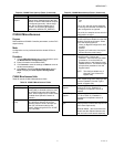
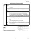
Fan Speed Switch
Define the type of switch used on the Wall module. Note that this setting also controls the maximum speed
setting of the fan. For example, if a three-speed fan is used, but the fan speed switch is set to two-speed, the
fan only operates with two speeds.
Normal
Settings based Switch Function
Setting
Fan speed switch function
No Fan Switch The fan speed switch is ignored
Three Position Off/Auto/On
Four Position Off/Auto/Low/High
Five Position Off/Auto/Low/Medium/High