


WEBVISION™
91 95-7769—01
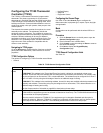
Configuring the XL15C Plant
Controller (XL15C)
The XL15C plant controller is designed to control HVAC
equipment and other miscellaneous loads in a distributed
control network. You can configure plant controller functions
such as start/stop loops, control loops, user-defined setpoint
values, math, and logic functions.
Control Functions
• 10 Control Loops
• 8 Start/Stop Loops
• 32 Logic Loops
• 32 Math Functions
• 6 Special Network Functions
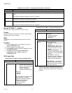
Navigating to XL15C Pages
To navigate to XL15C pages:
1. On the left pane click the required device name. The
Device Configuration page appears.
2. Click the Configuration tab. The Configuration page
appears.
Configuring the XL15C Controller
The options for configuring the XL15C Controller are as
follows:
• Local Inputs
• SetPoints (Loop Logic)
• Math Functions
• Control Loops
• Logic Loops
• Start Stop Loops
• Outputs
Configuring XL15C Local Inputs
The XL15C controller has 8 Analog Inputs and 8 Digital
Inputs.
ANALOG INPUTS
Analog Inputs are used to monitor external conditions, such
as temperature, humidity or pressure. These inputs are
commonly used for monitoring and as inputs to Control Loops,
Start /Stop Loops, Math Functions & Logic Loops.
Each Analog Input may be configured as Analog or Digital.
Analog Inputs configured as Analog can receive Input from
various types of sensors. Analog Inputs configured as Digital
can only receive digital signals as inputs
DIGITAL INPUTS
Digital Inputs are used to monitor external events, such as
contact closures (10 mA, 5Vdc). The contact closures initiate
alarms, monitor equipment status, and read pulse meters.
These inputs are commonly used as inputs to Control Loops,
Start /Stop Loops, Math Functions & Logic Loops.
Each Digital Input can be configured as Maintained,
Momentary, Counter Slow, Counter Fast, Pulse Meter.
An external digital input source is connected to the digital
input.
Poll Points
The XL15C controller utilizes poll points as a means to
retrieve data from other network devices. Data retrieved by a
poll point is available for linking to XL15C objects such as
math functions, control loops, logic loops, and start/stop loops.
The XL15C polls each point every two seconds. If the
response is not received within ten seconds the poll is
changed to once every 30 seconds. When the response is
received the poll rate returns to once every 2 seconds.
The XL15C controller supports a maximum of 20 poll points.
Purpose
Specify the attributes for up to eight analog inputs and the
sensor types and attributes for up to eight digital inputs.
Mode
Configuration can be performed with the wizard Off-line or
On-line.
Limits
Analog Input: One XL15C Plant controller supports up to
eight analog inputs (AI1 through AI8) as follows: 0 to 8,000
ohms (+-10 ohms), 0 to 10V dc, 4 to 20 mA, using an exter-
nal 500 ohm resistor with a 2-10V dc input, digital sensing
(contact closure).
Digital Input: Two of the four digital inputs can be configured
as counters. A counter counts the number of active inputs
within the range of 1 through 65,535. Pulse No. 65,536
automatically resets the counter to 0.
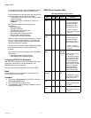
Procedure
1. On the Configuration page click the Local Inputs tab.
The Local Inputs page appears on the right pane.
2. To configure the Analog Inputs.
a. Select the input channel from Select Input.
b. Type a name in Input Name.
c. Select required input from Input Kind. The input
kind must be one of the following types for an ana-
log input:
• Unconfigured (default)
• Resistive
• Voltage
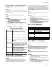
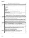
Default
Drive
Speed
Scale
-163.84 163.83 0% Default value for
nviDrvSpeedScale:
It provides scaling for
nviDrvSpeedStpt.
Negative values of
nviDrvSpeedScale indicate
reverse (anti clockwise)
direction of motor rotation.
This value will be adopted at
power-up and in case of not
receiving any input variable
within the specified Receive
Heartbeat time.
Table 69. NXVFD Drive Parameters. (Continued)
Point
Name
Min.
Value
Max.
Value
Typical
Value Description