


WEBVISION™
95-7769—01 84
Output Settings Section
Flow Type Defines the control flow algorithm used by the controller. The selection available dependents of the Pressure
Type and Box Type selected.
Valid selections for this field are:
• Flow Normal – This flow type is selectable when the Pressure Type is set to pressure independent and
the Box Type is set to Single Duct or Dual Duct.
• Shared Wall Module – This flow type is selectable when the Pressure Type is set to pressure
independent or pressure dependent and the Box Type is set to Single Duct.
• DD Satel No Flow Mix – This flow type is selectable when the Pressure Type is set to Pressure
Independent and the Box Type is set to Dual Duct.
• DD Satel Flow Mix – This flow type is selectable when the Pressure Type is set to Pressure Independent
and the Box Type is set to Dual Duct.
• DD Satel Constant Volume – This flow type is selectable when the Pressure Type is set to Pressure
Independent and the Box Type is set to Dual Duct.
• DD Master No Flow Mix – This flow type is selectable when the Pressure Type is set to Pressure
Independent and the Box Type is set to Dual Duct.
• DD Master Flow Mix – This flow type is selectable when the Pressure Type is set to Pressure
Independent and the Box Type is set to Dual Duct.
• DD Master Constant Volume – This flow type is selectable when the Pressure Type is set to Pressure
Independent and the Box Type is set to Dual Duct.
• Dual Duct Discharge Sensor – This flow type is selectable when the Pressure Type is set to Pressure
Independent and the Box Type is set to Dual Duct.
• Dual Duct Discharge Sensor Constant Volume – This flow type is selectable when the Pressure Type is
set to Pressure Independent and the Box Type is set to Dual Duct.
• Flow Tracking – This flow type is automatically selected when the Pressure Type is set to Pressure
Independent and the Box Type is set to Flow Tracking
Reheat Type Defines the type of reheat used by the controller. There are two basic types of reheat available for the VAV
Terminal, VAV Terminal Reheat and Peripheral Reheat.
Valid selections for this field are:
• No Reheat – There is no local reheat associated with the VAV Terminal.
• One Stage Reheat – There is one stage of electric reheat associated with the VAV Terminal. One triac
output is required for this option.
• Two Stage Reheat – There are two stage of electric reheat associated with the VAV Terminal. Two triac
outputs are required for this option.
• Three Stage Reheat – There are three stages of electric reheat associated with the VAV Terminal. Three
triac outputs are required for this option
• Three Stage Bin Reheat – There are three stages of electric reheat associated with the VAV Terminal.
The three stages are obtained by first turning on the first electric reheat for stage one, shutting down the
first stage and starting the second stage and finally turning both stages of electric reheat on for the third
stage. Two triac outputs are required for this option.
• One Stage Periph – There is one stage of electric peripheral reheat associated with the VAV Terminal.
One triac output is required for this option.
•Float Reheat – There is a modulating valve for the VAV Terminal reheat. This output uses the series 60
type floating control. Two triac outputs are required for this option.
• Float Periph Reheat – There is a modulating valve for the space peripheral reheat. This option uses the
series 60 type floating control for the output to the valve. Two triac outputs are required for this option.
• Float Reheat Then Periph – There is a modulating valve for the VAV Terminal reheat and a modulating
valve for the space peripheral reheat. This option uses the series 60 type floating control for both valve
outputs. The VAV Terminal reheat valve is modulated as the first stage of reheat and the peripheral reheat
valve is modulated open as the second stage. Four triac outputs are required for this option.
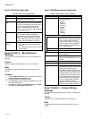
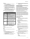
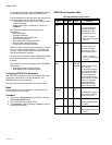
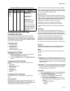
Table 62. Excel 10 VAV II - Configuration Parameters. (Continued)
Name Definition