


WEBVISION™
95-7769—01 38
Controller / Wall Module (continued)
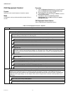
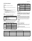
LED Occupancy
The LED shows the effective Occupancy mode. On indicates effective Occupied or Bypass, 1 Flash per Second indicates effective
Standby, Off indicates effective Unoccupied. 4 Flashes indicates the Controller answers of the Network Management Command
Wink.
LCD Display
This mode is used only for a Wall Module with LCD Display. The Display has following Symbols to show the Occupancy Modes: Sun
indicates effective Occupied or Bypass, Half Sun indicates effective Standby, Moon indicates effective Unoccupied. No Symbol and
OFF in 7-Segment indicates the Controller is Off. In the Off mode, a Snow Flag indicates whether Frost Protection is configured.
Blinking Symbols are used to show the Override: Blinking Sun indicates Override Occupied or Bypass, blinking Half Sun indicates
Override Standby, Blinking Moon indicates override unoccupied. The Controller answers with the Network Management Command
Wink with blinking Sun and Moon.
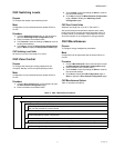
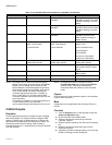
Override Button
Define how the override button on the connected wall module is to be used.
None
The wall module button is not used for bypass function.
ByPass Only
The Bypass button, when pressed, has two different functions depending on the length of time the button is held down:
Two seconds puts the controller in Bypass.
Five seconds puts the controller in Unoccupied.
Bypass
The Bypass button, when pressed, has the following function:
In two seconds the controller is in Bypass mode.
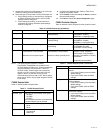
Setpoint Knob
The setpoint knob is available in different types of scale, and with different setpoint meanings, based on the country of usage. The
temperature engineering unit used (°C or °F) is the setting made in WebVision when creating the new project. That setting is used
for the total project. Note that the setpoint knob only affects the Occupied and Standby Setpoints. The Unoccupied setpoint is not
affected by the setpoint knob. Note that Version C and D Chilled Ceiling controllers have an on-board setpoint. They cannot be used
with an external TR21 or TR23 setpoint device.
The range of setpoint knob value lies between -9tdf to +9tdf.
No Knob
The setpoint knob is ignored. Note that this must be chosen if there is no setpoint knob connected to the controller. This selection
prevents the controller from reacting to incorrect setpoint values.
Relative
The setpoint knob is a relative knob, showing only a setpoint shift as (+) and (-) changes to the configured setpoint.
Absolute Middle
The setpoint knob is an absolute knob, showing the setpoint in absolute degrees. It is used as the space temperature setpoint
midway between the heating and cooling zero energy band.
Setpoint Limits
These two fields specify the allowed range of adjustment available from the wall module setpoint knob. This range is used by the
building manager for energy management purposes, to balance allowed comfort conditions with energy usage.
(SETPOINT KNOB = RELATIVE)
When the setpoint knob has been chosen as relative, the setpoint limits define the range of adjustment of the setpoint knob from the
zero point, in (DDC) for °C installations and (DDF) for °F installations.
(SETPOINT KNOB = ABSOLUTE MIDDLE)
When the setpoint knob has been chosen as absolute, the setpoint limits are limits on the absolute range of the setpoint knob in
(Deg.C) for °C installations and (Deg.F) for °F installations.
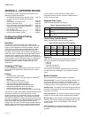
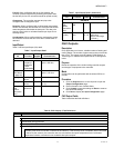
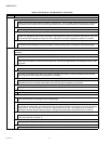
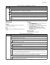
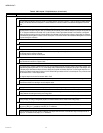
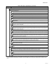
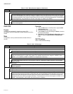
Table 9. CHC Inputs - Field Definitions. (Continued)
Name Field and Definition