


WEBVISION™
57 95-7769—01
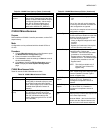
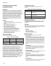
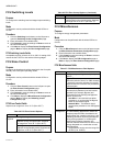
FCU Inputs
Purpose
To configure the wall module parameters and input points for a
FCU controller.
Mode
Configuration can be performed with the wizard Off-line or
On-line.
Procedure
1. Click the Inputs button on the left pane to open the
Input Configuration page.
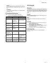
2. Enter information into available fields (see Table 33 on
page 58).
3. Click Commit to save the settings or Reset to revert to
the last saved settings.
4. Click Next to display the Equipment Control
Configuration page or Back to display the Output
Configuration page.
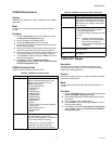
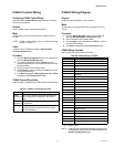
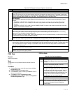
Control
Outputs
Configures the two control outputs for the different type of actuators and control sequences required for the
application.
Output 1 -
Mode
The output triac pair connected to terminals 13, 14, and 15 of the controller.
Select the control sequence option for Output 1. For four-pipe applications, the heating option is
recommended to minimize field wiring errors. For two-pipe applications, the changeover option is
the only selection.
Heat Mode The output is modulated open when heat energy is needed in the space.
Cool Mode The output is modulated open when cool energy is needed in the space
ChangeOver
Mode
The output is modulated open when heat or cool energy is needed in the space.
Not Used The output is not controlled by the controller and always remains off.
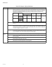
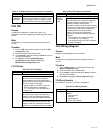
Output 1 -
Type
Select the type of actuator to be connected to the output.
Floating A three-point actuator that can be commanded open or closed. This type is on Terminals 14/15
and/or 17/18. The run times for the actuator are configured in the Equipment Control tab.
Floating Mid A three point actuator that can be commanded open or closed on terminals 14/15 and/or 17/18.
The run-times for the actuator are configured in the Outputs tab. The Zero Energy Position (no
Heat and no Cool) is the middle Position (50%). The Cool Range is 0 to 50%; the Heat Range, 50
to 100%. The Range can be reversed by selecting the Actuator Direct or Reverse Option. During
the Synchronization Process, the fan is turned off.
PWM Duty-cycled output where the 24VAC output is pulsed on/off in the duty cycle range: 0 percent to
100 percent. This type drives output Terminal 14 and/or 17.
One Stage Single-stage on/off output. This type switches Terminals 14 and/or 17.
Two Stage Two-stage on/off output. This type switches Terminal 14/17 for stage 1 and Terminal 15/18 for
stage 2.
Three Stage Three-stage switched output. The output switches Terminal 14/17 for stage 1 and Terminal 15/18
for stage 2. It switches both Terminals 14/15 and/or 17/18 for stage 3.
Thermal Switched on/off output. This type switches a 24V thermal actuator on Terminal 14/17.
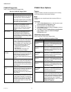
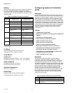
Output 2 -
Mode
The output triac pair connected to terminals 16, 17, and 18 of the controller.
Select the control sequence option for Output 2. For four-pipe applications, the Cool Mode option
is recommended to minimize field wiring errors. For two-pipe applications, the ChangeOver Mode
option is the only selection.
Output 2 -
Type
The selection options are the same as for Output 1.
Table 32. FCU Outputs - Fields and Definitions. (Continued)
Field Definition