


WEBVISION™
67 95-7769—01
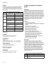
HYD Inputs
Purpose
To configure the wall module parameters and input points for a
HYD controller.
Mode
Configuration can be performed with the wizard Off-line or
On-line.
Procedure
1. Click the Inputs button on the left pane to open the
Input Configuration page.
2. Enter information into available fields.
3. Click Commit to save the settings or Reset to revert to
the last saved settings.
4. Click Next to display the Equipment Control
Configuration page or Back to display the Output
Configuration page.
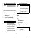
HYD Inputs fields
Control
Outputs
(cont.)
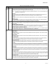
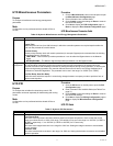
Output 2- Mode
Output triac pair connected to terminals 16/17/18 of the controller.
Select the control sequence option to be allocated to output 2. For four-pipe applications, always allocate this output to
the cool option to minimize field wiring errors. For two-pipe applications, you can select only the changeover option.
Output 2- Type
Selection options are the same as for Output 1.
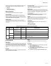
Table 43. Hydronic Controller Types and Outputs. (Continued)
Name Definition
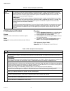
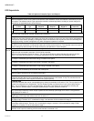
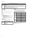
Table 44. Wall Module and Hydronic Controller Inputs.
Name Definition
Wall
Module
Configures the functionality of the connected wall module. Be careful that the features configured here are the same as
the features available on the wall module device to be connected.
Space Temp Sensor
Define whether or not the controller is to be used with a space temperature sensor connected to its input. Typically, a
space temperature sensor is used, but in cases where the space temperature is supplied from another device via the
network, the local space temperature sensor input is not used.
YES
The local space temperature sensor input is used. Ensure that a space temperature sensor is actually connected,
otherwise the controller measures incorrect values.
NO
The local space temperature sensor is not used. This option must be selected when a sensor is not connected.
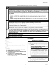
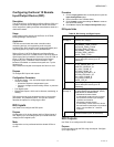
LED/LCD Display
This configuration defines whether a Wall Module with LED or a Wall Module with LCD Display is connected.
For the LED there is shown either the Override Status or the Effective Occupancy Status. The LCD Display shows the
both – the Effective and the Override Status and an additional Off Condition.
The Override Status results from the Scheduler, the Network Override, the Override Button and the Occupancy Sensor.
The Off Condition results from the Fanspeed Switch, the Window Contact and the Medium from nviApplicMode.
LED_OVERRIDE
The LED shows the Override from the Override Button or from the Network. On means Override Bypass, 1 Flash per
Second means Override Unoccupied, 2 Flashes per Second means Override Standby or Occupied. 4 Flashes
means the Controller answers of the Network Management Command Wink.
LED_OCCUPANCY
The LED shows the effective Occupancy Mode. On means effective Occupied or Bypass, 1 Flash per Second means
effective Standby, Off means effective Unoccupied. 4 Flashes means the Controller answers of the Network
Management Command Wink.
LCD_DISPLAY
This Mode is used only for a Wall Module with LCD Display. The Display has following Symbols to show the
Occupancy Modes: Sun means effective Occupied or Bypass, Half Sun means effective Standby, Moon means
effective Unoccupied. No Symbol and OFF in 7-Segment means the Controller is Off. In the Off Mode, a Snow Flag
indicates whether Frost Protection is configured. Blinking Symbols are used to show the Override: Blinking Sun
means Override Occupied or Bypass, blinking Half Sun means Override Standby, Blinking Moon means override
unoccupied. The Controller answers with of the Network Management Command Wink with blinking Sun and Moon.