WEBVISION™
87 95-7769—01
Excel 10 VAV II – Control Parameters
Use Table 64 to configure the Excel 10 VAV II Control
Parameters.
Purpose
Define Equipment Control parameters that the Excel 10 VAV II
controller uses to control the unitary equipment. Define VAV II
controller parameters.
Mode
Configuration can be performed with device On-line or
Off-line.
Procedure
1. Click the Control Parameters button on the left pane to
open the Control Parameters page.
2. Enter information into available fields.
3. Click Commit to save the settings or Reset to revert to
the last saved settings.
4. Click Next to display the PID Parameters page or Back
to display the Inputs page.
Excel 10 VAV II Control Parameters fields
Excel 10 VAV II – PID Settings
Use Table 65 to configure the Excel 10 VAV II PID values.
Purpose
Proportional-Integral-Derivative (PID) values regulate an
analog output based on two analog values (one is a controlled
variable; the other, a reference variable) and operating
parameters. The controlled variable is the variable that should
be held constant, for example, a room temperature. The
reference variable is the prescribed changeable value of the
controlled variable, for example, room temperature setpoint.
Define PID (Proportional Integral Derivative) parameters for a
VAV II Controller.
Mode
Configuration can be performed with the device On-line or
Off-line.
Procedure
1. Click the PID button on the left pane to open the PID
Parameters page.
2. Enter information into available fields.
3. Click Commit to save the settings or Reset to revert to
the last saved settings.
4. Click Next to display the Flow Pickup page or Back to
display the Control Parameters page.
Excel 10 VAV II PID Settings fields
Excel 10 VAV II – Flow Pickup
Use Table 66 to configure the Excel 10 VAV II flow pickup
settings.
Purpose
Specify differential pressure and velocity for flow sensors.
Define the differential pressures and velocities for the flow
sensors. These values would be used to calculate the flow
linearization values during the download sequence.
Mode
Configuration can be performed with the device On-line or
Off-line.
Procedure
1. Click the Flow Pickup button on the left pane to open
the Flow Pickup Table page.
2. Enter information into available fields (see Table 66 on
page 88).
3. Click Commit to save the settings or Reset to revert to
the last saved settings.
4. Click Next to display the Miscellaneous page or Back
to display the PID Parameters page.
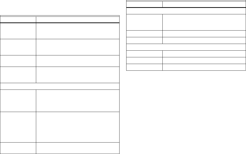
Table 64. VAV II Control Parameters.
Name Definition
Cooling Setpoints Values for the occupied, standby, and
unoccupied settings for the cooling
setpoints.
Heating Setpoints Values for the occupied, standby, and
unoccupied settings for the heating
setpoints.
Limits Values for the high and low limit settings
for the remote setpoint.
Flow Setpoints Values for the Maximum, Minimum, Max
Reheat, and Standby settings for the flow
setpoints.
Duct Settings
Area Area of the Duct. The user can choose a
CustomArea option for the Diameter and
enter a value for the area. The valid range
allowed is 0 to 4 ft
2
or 0 to 0.372 m
2
.
Diameter This list shows a predefined set of duct
diameters. The user can choose a
diameter option and the area will be
automatically calculated. Or, the user can
choose a “Custom Area” option and
manually enter the Area value.
Wall Module
Setpoint Limits
Values of the High Limit and Low Limit
setpoints on the wall module.
Table 65. VAV II PID Settings.
Name Definition
Cooling
Throttling Range Value ranges from 2 to 30 °F (-17 to -1 °C).
The Proportional gain value is equivalent
to the throttling range.
Integral Action Value ranges from 0 through 5,000 sec.
Derivative Action Value ranges from 0-255 sec.
Heating
Throttling Range Value ranges from 2 to 30 °F (-17 to -1 °C).
Integral Action Value ranges from 0 through 5,000 sec.
Derivative Action Value ranges from 0-255 sec.


