


WEBVISION™
175 95-7769—01
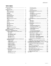
TOPIC INDEX
Product Description ....................................................... 1
Approvals 1
Operation and Use ......................................................... 2
Sign-in ........................................................................ 2
Password Reminder .................................................. 2
Working with Tables ................................................... 3
Graphics .................................................................... 3
Schedules .................................................................. 5
Assign Devices .......................................................... 6
Define Special Event .................................................. 6
Delete Schedules ....................................................... 7
Replicate Schedule .................................................... 7
Alarms ........................................................................ 8
Alarm Configuration and Use ..................................... 9
Trends ........................................................................ 10
Trend Setup and Use ................................................. 12
Users ......................................................................... 13
Devices ...................................................................... 16
Point List .................................................................... 19
Device Configuration ................................................. 19
Set Points .................................................................. 20
Sensor Calibration ..................................................... 20
Balancing ................................................................... 20
Demand Limit Control (DLC) ..................................... 21
System ....................................................................... 24
Migration of LCBS Sites in WebVision ....................... 29
Warranty and Returns ................................................... 33
Appendix A – Supported Devices ................................ 34
Configuring Chilled Ceiling Controllers (CHC)............ 34
CHC Outputs.......................................................... 35
CHC Inputs ............................................................ 37
CHC Equipment Control ........................................ 40
CHC Switching Levels ........................................... 41
CHC Zone Control ................................................. 41
CHC Miscellaneous ............................................... 41
CHC PID ................................................................ 42
CHC Wiring Diagram ............................................. 43
Configuring the Constant Volume Air Handling Unit
Controllers (CVAHU)................................................... 43
CVAHU Outputs ..................................................... 44
CVAHU Inputs........................................................ 46
CVAHU Equipment Control.................................... 48
CVAHU Economizer............................................... 49
CVAHU HC Stages................................................. 49
CVAHU Zone Options............................................ 50
CVAHU Miscellaneous........................................... 51
CVAHU PID............................................................ 52
CVAHU Custom Wiring.......................................... 53
CVAHU Wiring Diagram......................................... 53
Configuring Fan Coil Unit Controllers (FCU) .............. 54
FCU Outputs.......................................................... 55
FCU Inputs............................................................. 57
FCU Equipment Control......................................... 60
FCU Fan ................................................................ 61
FCU Switching Levels............................................ 62
FCU Zone Control .................................................. 62
FCU Miscellaneous ................................................ 62
FCU PID................................................................. 63
FCU Wiring Diagram .............................................. 63
Configuring Hydronic Controllers (HYD) ..................... 64
HYD Outputs .......................................................... 65
HYD Inputs............................................................. 67
HYD Equipment Control Outputs............................ 69
HYD Switching Levels............................................ 70
HYD Zone Control.................................................. 70
HYD Miscellaneous Parameters............................. 71
HYD PID................................................................. 71
HYD Wiring............................................................. 72
Configuring the Excel 10 Remote Input/Output Device
(RIO) ........................................................................... 73
RIO Inputs .............................................................. 73
RIO Outputs............................................................ 73
RIO Deltas..............................................................74
Configuring the Unit Ventilator (UV)............................ 74
UV Outputs............................................................. 75
UV Inputs................................................................ 75
UV Equipment Control Options .............................. 76
UV Economizer Settings ........................................ 77
UV Heating/Cooling (H/C) Stages .......................... 78
UV Zone Options.................................................... 79
UV Miscellaneous Settings..................................... 79
UV PID settings...................................................... 80
UV Outputs Wiring Assignment.............................. 81
UV Controller Wiring Diagram................................ 82
Configuring the Excel 10 VAV II Controller.................. 82
Excel 10 VAV II – Inputs ......................................... 86
Excel 10 VAV II – Control Parameters.................... 87
Excel 10 VAV II – PID Settings............................... 87
Excel 10 VAV II – Flow Pickup................................ 87
Excel 10 VAV II – Miscellaneous Settings .............. 88
Excel 10 VAV II – Custom Wiring Settings ............. 88
Excel 10 VAV II – Wiring Diagram .......................... 89
Configuring the Vacon NX Frequency Converter
(NXVFD)...................................................................... 89
Configuring the XL15C Plant Controller (XL15C)........ 91
Configuring the T7350 Thermostat Controller (T7350) 97
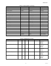
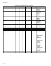
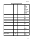
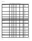
Appendix B – Device Point Tables ................................ 106
W7763C/D/E Chilled Ceiling Controller (CHC) ...........106
Constant Volume Air Handling Unit Controller
(CVAHU)......................................................................114
Fan Coil Unit Controller (FCU) ....................................122
Hydronic Controller (HYD) ..........................................129
Excel 10 Remote Input/Output Device (RIO) ..............136
Unit Ventilator (UV) .....................................................138
Excel 10 VAV II Controller (VAV II)..............................145
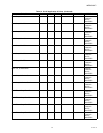
Vacon NX Frequency Converter (NXVFD)..................152
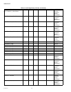
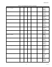
XL15C Plant Controller (XL15C).................................155
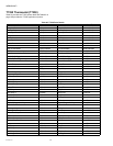
T7350 Thermostat (T7350) .........................................168
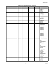
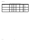
Topic Index ...................................................................... 175