


8. Getting started
8.6.2.2.2 Defining the Panel Markers
Panel Marker
Adefined area on a projected channel image. Acuras measurements are to be performed at these areas.
Introduction
By default, five Panel Markers need to be user defined (quadrangular image). Optionally, the position of two of the four additional
automatically calculated Panel Markers can be changed.
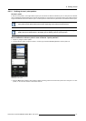
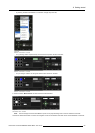
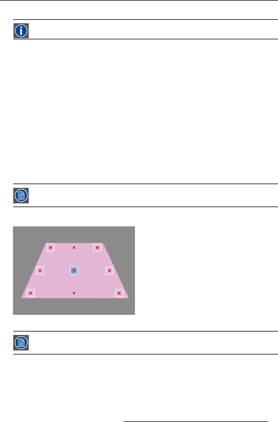
If a new Acuras Multipoint position is created, the nine Panel Markers appear on the projected image at their default position:
• a moveable Panel Marker is indicated by a white outline having a small green or red square in it on the projected image and
by a white outline on the GUI.
• a Panel Marker that can not be moved is indicated by a small green or red square only on the projected image.
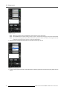
• a focused Panel Marker is indicated by a blue background on the projected image and on the GUI: this Panel Marker can be
selected to be moved or the Gimbal arrows can be used to jump to another Panel Marker.
• a selected Panel Marker is indicated by a white background on the projected image and on the GUI: the Gimbal control arrows
canbeusedtomoveitsposition.
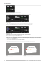
• a small red square in the center of a Panel Marker on the projected image indicates that no Gimbal position is available for this
Panel Marker.
• a small green square in the center of a Panel Marker and a green check mark in the GUI indicate that a Gimbal position is
available for this Panel Marker.
• in case of a triangular visible image, two Panel Markers are indicated by a thin white outline on the GUI, which means that they
are currently coinciding with another Panel Marker and therefore not available.
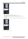
Next to the definition of the Panel Marker position, the Panel Marker size can be changed. The recommended size is determined
by the area covered by the spectrometer at that particular part of the image on the screen, that in turn is determined by the distance
between spectrometer and screen at that location.
The Field of View (FOV) value o f the spe ctrometer cu rrently installed on the AutoAlignment H ead is 8 degrees.
The size of each Panel Marker can be individually defined i.e. changing the size o
f one Panel Marker does not affect or change the
size of other Panel Markers.
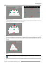
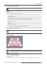
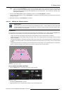
Visible image area
Image 8-37
Panel Markers in the quadrangular shape (Panel Marker Center is focused)
If you have defined multiple Head location in the Options page, make sure t hat the physical position o f your
AutoAlignment Head corresponds to the head location in the XDS RACU user interface prior to defining the
Acuras Multi-point position.
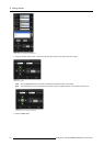
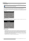
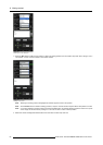
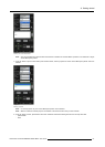
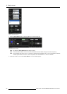
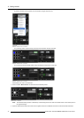
How to define the Panel Markers?
This procedure applies to the quadrangular image.
1. Project an image.
2. On the Positioning Page, navigate to Position > P osition type and select Acuras Multi-point from the drop down list.
R59770509 AUTOALIGNMENT HEAD GEN II 26/11/2013
65