


6. Specifications
6. SPECIFICATIONS
Overview
• Hardware layout
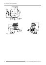
• Gimbal range
• Camera FOV
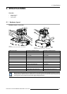
6.1 Hardware layout
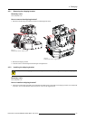
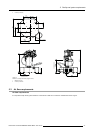
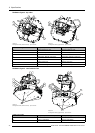
Hardware layout: front view
K
J
I
H
F
G
D
E
BA C
Image 6-1
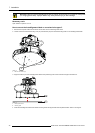
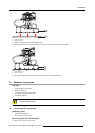
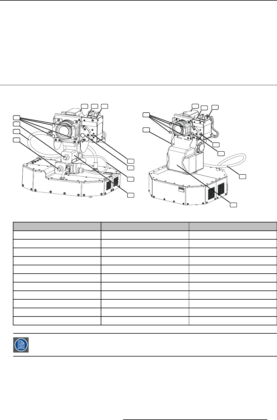
AutoAlignment Head (standard version) : parts overview
I
A
B
C
K
D
E
G
F
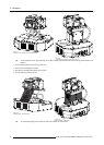
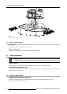
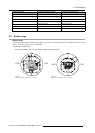
Image 6-2
AutoAlignment Head (rugged version) : parts overview
Label in the image
Description (standard version) Description (rugged version)
A
Camera Camera
B
Spectrometer Spectrometer
C
Laser pointer Laser pointer
D Laser aperture Laser aperture
E
Optical filter Optical filter
F
Gimbal cable
PAN–TILT unit cable
G Gimbal Gimbal (PAN–TILT unit)
H
Manual pan knob (See note)
not available
I
Camera cable Camera cable
J
Manual tilt knob (See note)
not available
K
Thumb screws to fix the focus ring Thumb screws to fixthefocusring
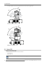
Manual pan and tilt adjustment by using the knobs is only allowed when the AutoAlignment Head is not elec-
trically powered. W hen the device is powered up, the manual pan and tilt knobs are blocked electronically.
Forcing a pan or tilt movement via the knobs might damage the device.
R59770509 AUTOALIGNMENT HEAD GEN II 26/11/2013 31