


12. Operating AutoGeometry: Warp display
12. OPER ATING AUTOGEOMETRY: WA RP DISPLAY
About this chapter
This chapter describes how to perform the Warp AutoGeometry Capture process. Next to that, performing Warp AutoGeometry
Realignment and deleting a Warp Realignment data are discussed.
12.1 AutoGeometry Capture
AutoGeometry Capture
The capture process is run to make the XDS RACU learn the relative positions of the non-distorted AutoGeometry dots projected
by the projector with respect to the reference dots from the LDATs or slide projector.
During the warp capturing process, series of AutoGeometry patterns having dots arranged in a linear manner (both horizontally and
vertically) displayed by the projector and captured by the AutoAlignment Head camera.
The capture data obtained as a result of the warp capture process can be used in multiple warp realignment situations. It can be
used to correct the geometrical errors occurs because of the projector replacement or mechanical shifts. Also, it can be used to
correct the geometrical error introduced by the insertion of a blend plate in the projector(s) light path.
Three options are available for the user to generate the AutoGeometry dot pattern.
• Polaris;
•Projector;
• Image Generator.
Each option has its own prerequisite, which must be completed prior to starting the Warp AutoGeometry Capture process.
Prerequisite for Polaris
1. SimCAD file created for this display setup should be available;
2. Polaris software is installed on the master IG and on the slave IGs connected to their corresponding projectors in the display
system;
3. Polaris Master PC is connected to the XDS RACU MCU through the network (LAN).
4. Polaris slave is launched on the slave IG of the projector for which the capture is to be executed;
5. Polaris Master is launched on the master IG.
Prerequisite for Projector
Make sure that external source(s) must be connected to the projector generating the AutoGeometry dot patterns.
Prerequisite for Image Generator
1. Make sure that application running on the Image Generator able to communicate with the XDS RACU software via XDS RACU
API;
2. Make sure that application can draw AutoGeometry dot pattern on the Image Generator when received a request for it from the
XDS RACU software.
Make sure that the A utoGeom etry position is defined for e ach projector in the selected group where you wish
to run the Warp AutoGeometry Capture.
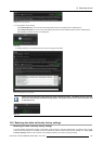
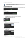
How to start the Warp AutoGeometry Capture process?
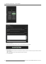
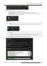
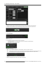
1. Open the SimCAD file through the Barco Polaris Master window.
2. Navigate to O ptions > A uto Alignment > Warp AutoGeometry and do the following
a) check Enable Warp Auto Geometry check box.
b) select a pattern generator option from the Dot Pattern Generator drop down list as required.
Note: Dot Pattern G enerator is a password-protected item; a secret password is required!
R59770509 AUTOALIGNMENT HEAD GEN II 26/11/2013 137