


List of images
LIST OF IMAGES
2-1 Labels: position........................................................................................................ 9
2-2 Labels: position........................................................................................................ 9
2-3 Labels: position........................................................................................................ 9
2-4 Labels: position.......................................................................................................10
2-5 Labels: position.......................................................................................................10
2-8 Emergency button + label............................................................................................13
2-9 Moving parts warning label...........................................................................................14
2-10 Moving parts warning label...........................................................................................14
2-11 Laserwarninglabel...................................................................................................14
2-12 Laserwarninglabel...................................................................................................14
2-14 SFTP Cat.5e cable warning label....................................................................................15
3-1 EMCshieldingclamp.................................................................................................17
4-1 Lifting instructions: Barco (standard and rugged) version ..........................................................19
4-2 Packaging: contentofthemainbox.................................................................................20
4-3 Packaging: remove the foam parts (AutoAlignment Head standard version)......................................21
4-4 Packaging: remove the foam parts (AutoAlignment Head rugged version)........................................22
4-5 Shipping bracket removal: standard version ........................................................................23
4-6 Shipping bracket removal: rugged version ..........................................................................23
4-7 Orientation to fix shipping bracket: standard version ...............................................................24
4-8 Orientation to fix shipping bracket: rugged version .................................................................24
4-9 Shipping bracket: standard version..................................................................................24
4-10 Shippingbracket: ruggedversion....................................................................................24
5-1 Dimension: AutoAlignment Head (standard version) ...............................................................26
5-2 Dimension: AutoAlignment Head (rugged version) .................................................................27
5-3 AutoAlignment Head : position of air grids .........................................................................28
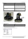
6-1 AutoAlignment Head (standard version) : parts overview ..........................................................31
6-2 AutoAlignment Head (rugged version) : parts overview ............................................................31
6-3 AutoAlignment Head (standard version) : parts overview ..........................................................32
6-4 AutoAlignment Head (rugged version) : parts overview ............................................................32
6-5 AutoAlignment Head (standard version) : parts overview ..........................................................32
6-6 AutoAlignment Head (rugged version) : parts overview ............................................................32
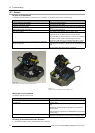
6-7 AutoAlignment Head (standard version) : Pan range...............................................................33
6-8 AutoAlignment Head (rugged version) : Pan range.................................................................33
6-9 AutoAlignment Head (standard version) : Tilt range ................................................................34
6-10 AutoAlignment Head (rugged version) : Tilt range ..................................................................34
7-1 Lifting instructions: AutoAlignment Head (standard and rugged) version..........................................35
7-6 preparation: making a loop ..........................................................................................38
7-7 preparation: fixingtheloop...........................................................................................38
7-8 preparation: fixingtheloopattheotherendofthecable...........................................................38
7-9 preparation: placing the cable on the warning label ................................................................38
7-10 preparation: fixing the warning label.................................................................................38
7-11 preparation: fixing the warning label at the other end of the cable .................................................38
7-12 Connectors: mains power (MCU)....................................................................................38
7-13 Connectors: mains power (AutoAlignment Head)...................................................................39
7-15 Connecting SFTP Cat.5e cable to LEX unit .........................................................................40
7-16 Connecting SFTP Cat.5e cable to LEX unit .........................................................................40
7-17 Connection diagram..................................................................................................40
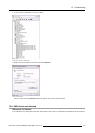
7-18 XDSRACUServer Console .........................................................................................42
7-19 Spectrometer: serial number ........................................................................................42
7-20 XDSRACUServer Console .........................................................................................42
7-21 Camerasettings......................................................................................................44
7-22 Zoom: looseningthefourscrews....................................................................................45
7-23 Zoom: tighteningthe fourscrews....................................................................................45
7-24 Focus: loosening4thumbscrews....................................................................................46
7-25 Focus: tightening 4thumbscrews....................................................................................46
7-26 AutoAlignment settings: Acuras parameters ........................................................................47
7-27 AutoAlignment settings: AutoGeometry parameters
................................................................47
7-28 AutoAlignment settings: OmniBlend parameters....................................................................48
7-29 AutoAlignment settings: Warp AutoGeometry parameters .........................................................48
8-1 StartinguptheMCU..................................................................................................49
8-2 StartinguptheeRACU...............................................................................................50
8-3 Starting up the AutoAlignment Head ................................................................................50
8-4 Connection dialog ....................................................................................................51
8-5 Connect: button ......................................................................................................51
8-6 MainpageoftheXDSRACUforthe selected display isdisplayed ................................................52
8-7 Activatingthe plugins.................................................................................................52
8-8 Options page: definingtheheadlocation ...........................................................................53
8-9 Naming the head location............................................................................................53
8-10 Adding the head location.............................................................................................53
8-11 Selecting the head loacation.........................................................................................54
8-12 Renaming the head location .........................................................................................54
8-13 Saving the renamed head location ..................................................................................54
8-15 GimbalHomePosition ...............................................................................................54
R59770509 AUTOALIGNMENT HEAD GEN II 26/11/2013
171