


93
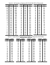
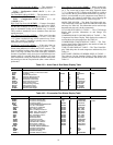
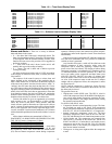
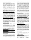
Table 112 — Time Guard Display Table
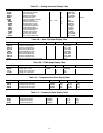
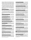
Table 113 — Software Version Numbers Display Table
Alarms and Alerts — There are a variety of different
alerts and alarms in the system.
• P — Pre-Alert: Part of the unit is temporarily down. The
alarm is not broadcast on the CCN network. The alarm relay
is not energized. After an allowable number of retries, if the
function does not recover, the pre-alert will be upgraded to
an alert or an alarm.
• T — Alert: Part of the unit is down, but the unit is still
partially able to provide cooling or heating.
• A — Alarm: The unit is down and is unable to provide
cooling or heating.
All alarms are displayed with a code of AXXX where the A
is the category of alarm (Pre-Alert, Alert, or Alarm) and XXX
is the number.
The response of the control system to various alerts and
alarms depends on the seriousness of the particular alert or
alarm. In the mildest case, an alert does not affect the operation
of the unit in any manner. An alert can also cause a “strike.” A
“striking” alert will cause the circuit to shut down for 15 min-
utes. This feature reduces the likelihood of false alarms causing
a properly working system to be shut down incorrectly. If three
strikes occur before the circuit has an opportunity to show that
it can function properly, the circuit will strike out, causing the
shutdown alarm for that particular circuit. Once activated, the
shutdown alarm can only be cleared via an alarm reset.
Circuits with strikes are given an opportunity to reset their
strike counter to zero. As discussed above, a strike typically
causes the circuit to shut down. Fifteen minutes later, that
circuit will once again be allowed to run. If the circuit is able to
run for 1 minute, its replacement circuit will be allowed to shut
down (if not required to run to satisfy requested stages). How-
ever, the “troubled” circuit must run continuously for 5 minutes
with no detectable problems before the strike counter is reset to
zero.
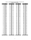
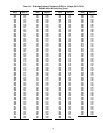
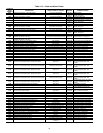
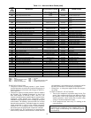
All the alarms and alerts are summarized in Table 114.
DIAGNOSTIC ALARM CODES AND POSSIBLE CAUSES
T051, P051 (Circuit A, Compressor 1 Failure)
T052, P052 (Circuit A, Compressor 2 Failure)
T055, P055 (Circuit B, Compressor 1 Failure)
T056, P056 (Circuit B, Compressor 2 Failure) — Alert codes
051, 052, 055, and 056 are for compressors A1, A2, B1, and
B2 respectively. These alerts occur when the current sensor
(CS) does not detect compressor current during compressor
operation. When this occurs, the control turns off the compres-
sor and logs a strike for the respective circuit. These alerts reset
automatically.
If the current sensor board reads OFF while the compressor
relay has been commanded ON for a period of 4 continuous
seconds, an alert is generated.
Any time this alert occurs, a strike will be called out on the
affected compressor. If three successive strikes occur the
compressor will be locked out requiring a manual reset or
power reset of the circuit board. The clearing of strikes during
compressor operation is a combination of 3 complete cycles or
15 continuous minutes of run time operation. So, if there are
one or two strikes on the compressor and three short cycles
(ON-OFF, ON-OFF, ON-OFF) less than 15 minutes each
occur, the strikes will be reset to zero for the affected compres-
sor. Also, if the compressor turns on and runs for 15 minutes
straight with no compressor failure, the compressor’s strikes
are cleared as well.
NOTE: Until the compressor is locked out, for the first two
strikes, the alert will not be broadcast to the network, nor will
the alarm relay be closed.
The possible causes are:
• High-pressure switch (HPS) open. The HPS is wired in
series with compressor relays on the MBB. If the high-pres-
sure switch opens during compressor operation, the com-
pressor stops, and the CS no longer detects current, causing
the control to activate this alert.
For 48/50AJ,AK,AW,AY units:
• Compressor internal overload protection is open. The inter-
nal overloads are used on the Scroll Tech compressors
(black) and smaller Maneurop compressors used on the size
020, 025, 027, 030, 035 units and 040 A1, A2 compressors.
• Internal compressor temperature sensor trip. The large
Maneurop compressors (blue) used on the size 040 (B1,
B2), 050, and 060 units have an internal temperature sensor.
• Circuit breaker trip. The compressors are protected from
short circuit by a breaker in the control box. On the size
020-035 and 040 A1, A2 units there is one breaker per two
compressors and on the size 040 (B1, B2), 050, and 060
compressors there is one breaker per compressor because
there are not internal overloads.
• Wiring error. A wiring error might not allow the compressor
to start.
ITEM EXPANSION RANGE UNITS POINT WRITE STATUS
TMGD TIMEGUARDS
TG.A1 Compressor A1 Timeguard CMPA1_TG
TG.A2 Compressor A2 Timeguard CMPA2_TG
TG.B1 Compressor B1 Timeguard CMPB1_TG
TG.B2 Compressor B2 Timeguard CMPB2_TG
TG.H1 Heat Relay 1 Timeguard HS1_TG
TG.H2 Heat Relay 2 Timeguard HS2_TG
TG.H3 Heat Relay 3 Timeguard HS3_TG
TG.H4 Heat Relay 4 Timeguard HS4_TG
TG.H5 Heat Relay 5 Timeguard HS5_TG
TG.H6 Heat Relay 6 Timeguard HS6_TG
ITEM EXPANSION RANGE UNITS POINT WRITE STATUS
VERS SOFTWARE VERSION NUMBERS
MBB CESR131343-xx-xx string
ECB1 CESR131249-xx-xx string
ECB2 CESR131249-xx-xx string
SCB CESR131226-xx-xx string
CEM CESR131174-xx-xx string
MARQ CESR131171-xx-xx string
NAVI CESR130227-xx-xx string