


117
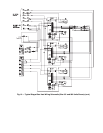
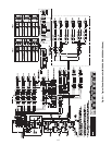
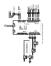
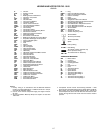
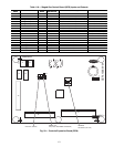
LEGEND AND NOTES FOR FIG. 15-25
LEGEND
NOTES:
1. Factory wiring is in accordance with the National Electrical
Codes. Any field modifications or additions must be in compli-
ance with all applicable codes.
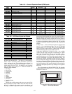
2. Use 75° C min wire for field power supply, use copper wires for
all units.
3. All circuit breakers “Must Trip Amps” are equal to or less than
156% RLA.
4. Compressor and fan motors are thermally protected — three
phase motors protected against primary single phase conditions.
5. Red jumper wire must be added between R, W1, and W2 for
space temperature sensor and all VAV units with heat and tem-
porarily during Service Test mode when the heaters need to
operate.
A—Circuit A
AUX — Auxiliary Contact
B—Circuit B
BP — Building Pressure Transducer
C—Contactor, Compressor
CAP — Capacitor
CB — Circuit Breaker
CCB — Control Circuit Breaker
CCH — Crankcase Heater
CCN — Carrier Comfort Network
®
CEM — Controls Expansion Module
COMP — Compressor Motor
CR — Control Relay
CS — Compressor Safety
CSB — Compressor Current Sensing Board
DP — Duct Pressure Sensor
DPT — Discharge Pressure Transducer
DS — Disconnect Switch
ECB-1 — Economizer Control Board
ECB-2 — Building and Supplier Air Control Board
EDT — Evaporator Discharge Air Temperature
FIOP — Factory-Installed Option
FS — Flame Sensor
FU — Fuse
GND — Ground
HC — Heat Contactor
HGBP — Hot Gas Bypass
HIR — Heat Interlock Relay
HPS — High Pressure Switch
HR — Heat Relay
HS — Hall Effect Induced Draft Motor Switch
IAQ — Indoor Air Quality
IDF — Induced Draft Fan
IDM — Induced Draft Motor
IFC — Indoor Fan Contactor
IFCB — Indoor Fan Circuit Breaker
IFM — Indoor Fan Motor
IGC — Integrated Gas Control Board
IP — Internal Compressor Protector
LAT — Staged Gas Temperature Sensor
LEN — Local Equipment Network
LS — Limit Switch
MBB — Main Base Board
MGV — Main Gas Valve
NEC — National Electrical Code
OARH — Outdoor Air Relative Humidity
OAT — Outdoor Air Temperature Sensor
OFC — Outdoor Fan Contactor
OFM — Outdoor Fan Motor
PEC — Power Exhaust Contactor
PEM — Power Exhaust Motor
PL — Plug
RARH — Return Air Relative Humidity
RAT — Return Air Temperature Sensor
RLA — Rated Load Amps
RLY — Relay
RS — Rollout Switch
SCB — Staged Gas Heat Control Board
SCT — Saturated Condensing Temperature Sensor
SDU — Scrolling Marquee Display
SST —
Saturated Suction Temperature Sensor
T-55 — Room Temperature Sensor
T-56 — Room Temperature Sensor with Setpoint
TB — Terminal Block
TRAN — Transformer
VAV — Variable Air Volume
VFD — Variable Frequency Drive
Terminal Block
Terminal (Unmarked)
Terminal (Marked)
Splice
Factory Wiring
Field Wiring
To indicate common potential only.
Not to represent wiring.
To Indicate FIOP or Accessory
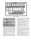
THERMOSTAT MARKINGS
BM — Blower Motor
C—Common
CM — Inducer Motor
CS — Centrifugal Switch
G—Fan
IFO — Indoor Fan On
L1 — Line 1
R—Thermostat Power
RT — Power Supply
SS — Speed Sensor
W1 — Thermostat Heat Stage 1
W2 — Thermostat Heat Stage 2
X—Alarm Output
Y1 — Thermostat Cooling Stage 1
Y2 — Thermostat Cooling Stage 2