


132
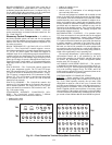
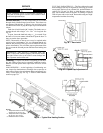
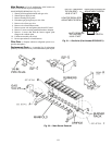
Condenser-Fan Adjustment
NOTE: Condenser fans on size 060 MCHX units are not
adjustable.
1. Turn off unit power supply.
2. Remove fan guard.
3. Loosen fan hub setscrews.
4. Adjust fan height on shaft using a straightedge placed
across venturi and measure per Fig. 43.
5. Fill hub recess with permagum if rubber hubcap is missing.
6. Tighten setscrews and replace panel(s).
7. Turn on unit power.
Four-Inch Filter Replacement — The 4-Inch Filter
Change Mode variable is used to service the unit when 4-in.
filters are used. When the filters need to be changed, set
Service Test
F.4. CH = YES. The unit will be placed in
Service Test mode and the economizer will move to the 40%
open position to facilitate removal of the 4-in. filters. After the
filters have been changed, set Service Test
F.4 .CH = NO to
return the unit to normal operation.
Power Failure — The economizer damper motor is a
spring return design. In event of power failure, dampers will
return to fully closed position until power is restored.
Refrigerant Charge — Amount of refrigerant charge is
listed on unit nameplate. Refer to Carrier GTAC II; Module 5;
Charging, Recovery, Recycling, and Reclamation section for
charging methods and procedures.
Unit panels must be in place when unit is operating during
charging procedure.
NOTE: Do not use recycled refrigerant as it may contain
contaminants.
NO CHARGE — Use standard evacuating techniques. After
evacuating system, weigh in the specified amount of refriger-
ant from the unit nameplate.
LOW CHARGE COOLING
All Units with Round Tube-Plate Fin Condenser Coils
—
Connect the gage set and a temperature-measuring device to
the liquid line. Ensure that all condenser fans are operating. It
may be necessary to block part of the coil on cold days to
ensure that condensing pressures are high enough to turn on
the fans. Adjust the refrigerant charge in each circuit to obtain
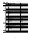
state point liquid subcooling for specific models as listed in
Table 123.
NOTE: Indoor-air cfm must be within normal operating range
of unit.
Table 123 – Round Tube, Plate Fin Unit Charge
48/50A2,A3,A4,A5 Units with MCHX Condenser
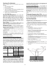
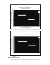
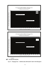
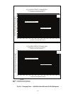
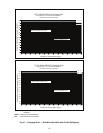
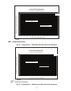
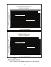
— Due
to the compact, all aluminum design, microchannel heat
exchangers will reduce refrigerant charge and overall operating
weight. As a result, charging procedures for MCHX units
require more accurate measurement techniques. Charge should
be added in small increments. Using cooling charging charts
provided (Fig. 44-50), add or remove refrigerant until condi-
tions of the chart are met. As conditions get close to the point
on the chart, add or remove charge in
1
/
4
lb increments until
complete. Ensure that all fans are on and all compressors are
running when using charging charts.
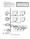
To Use the Cooling Charging Chart
— Use the outdoor air
temperature, saturated suction temperature and saturated con-
densing temperature (available on the ComfortLink™ display),
and find the intersection point on the cooling charging chart. If
intersection point is above the line, carefully recover some of
the refrigerant. If intersection point is below the line, carefully
add refrigerant.
NOTE: Indoor-air cfm must be within normal operating range
of unit.
Thermostatic Expansion Valve (TXV) — Each circuit
has a TXV. The TXV is adjustable and is factory set to maintain
8 to 12° F superheat leaving the evaporator coil. The TXV con-
trols flow of liquid refrigerant to the evaporator coils. Adjusting
the TXV is not recommended.
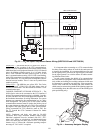
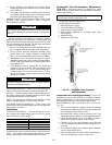
Gas Valve Adjustment
NATURAL GAS — The 2-stage gas valve opens and closes
in response to the thermostat or limit control.
When power is supplied to valve terminals 3 and 4, the pilot
valve opens to the preset position. When power is supplied to
terminals 1 and 2, the main valve opens to its preset position.
The regular factory setting is stamped on the valve body
(3.5 in. wg).
To adjust regulator:
1. Set thermostat at setting for no call for heat.
2. Switch main gas valve to OFF position.
3. Remove
1
/
8
-in. pipe plug from manifold. Install a water
manometer pressure-measuring device.
4. Switch main gas valve to ON position.
5. Set thermostat at setting to call for heat (high fire).
6. Remove screw cap covering regulator adjustment screw
(See Fig. 51).
7. Turn adjustment screw clockwise to increase pressure or
counterclockwise to decrease pressure.
8. Once desired pressure is established, set unit to no call for
heat (3.3-in. wg high fire).
9. Switch main gas valve to OFF position.
10. Remove pressure-measuring device and replace
1
/
8
-in.
pipe plug and screw cap.
11. Turn main gas valve to ON position and check heating
operation.
UNIT
48/50
REFRIGERANT
TYPE
SIZE
LIQUID
SUBCOOLING
AJ,AK,AW,AY R-22
020, 025, 027,
030, 035, 040,
050, 060
20 F ± 2 F
036 18 F ± 2 F
041, 051 15 F ± 2 F
A2,A3,A4,A5 R-410A
020, 027, 040,
050, 060
15 F ± 2 F
030, 035 20 F ± 2 F
025 12 F ± 2 F
A
Fig. 43 — Condenser-Fan Adjustment
(All Units Except Size 060 MCHX)
UNIT SIZE DIMENSION “A” (in.)
020-035, 050 1.30 ± 0.12
036-041, 051, 060 0.87 ± 0.12