


90
Forcing Inputs and Outputs — Many variables may
be forced both from the CCN and directly at the local display.
This can be useful during diagnostic testing and also during
operation, typically as part of an advanced third party control
scheme. See Appendices A and B.
NOTE: In the case of a power reset, any force in effect at the
time of the power reset will be cleared.
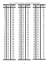
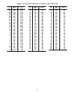
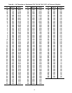
CONTROL LEVEL FORCING — If any of the following
points are forced with a priority level of 7 (consult CCN litera-
ture for a description of priority levels), the software clears the
force from the point if it has not been written to or forced again
within the timeout periods defined below:
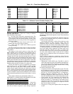
Run Status Menu — The Run Status menu provides the
user important information about the unit. The Run Status table
can be used to troubleshoot problems and to help determine
how and why the unit is operating.
AUTO VIEW OF RUN STATUS — The Auto View of Run
Status display table provides the most important unit informa-
tion. The HVAC Mode (Run Status
VIEW
HVAC) in-
forms the user what HVAC mode the unit is currently in. Refer
to the Modes section on page 32 for information on HVAC
modes. The occupied status, unit temperatures, unit set points,
and stage information can also be shown. See Table 105.
Run Status
VIEW
HVAC — Displays the current HVAC
Mode(s) by name. HVAC Modes include:
OFF VENT HIGH HEAT
STARTING UP HIGH COOL FIRE SHUT DOWN
SHUTTING DOWN LOW COOL PRESSURIZATION
DISABLED UNOCC FREE COOL EVACUATION
SOFTSTOP REQUESTTEMPERING HICOOL SMOKE PURGE
REM SW DISABLE TEMPERING LOCOOL
COMP STUCK ON TEMPERING VENT
TEST LOW HEAT
Run Status
VIEW
OCC — This variable displays the cur-
rent occupancy status of the control.
Run Status
VIEW
MAT — This variable displays the cur-
rent value for mixed-air temperature. This value is calculated
based on return-air and outside-air temperatures and economiz-
er damper position.
Run Status
VIEW
EDT — This variable displays the cur-
rent evaporator discharge air temperature during Cooling
modes. This value is read at the supply air thermistor location
(or at cooling coil thermistor array if unit is equipped with hy-
dronic heating coil).
Run Status
VIEW
LAT — This variable displays the cur-
rent leaving-air temperature during Vent and Hydronic Heating
modes. This value is read at the supply air thermistor location.
Run Status
VIEW
EC.C.P — This variable displays the
current economizer control point value (a target value for air
temperature leaving the evaporator coil location).
Run Status
VIEW
ECN.P — This variable displays the
current actual economizer position (in percentage open).
Run Status
VIEW
CL.C.P — This variable displays the
current cooling control point (a target value for air temperature
leaving the evaporator coil location).
Run Status
VIEW
C.CAP — This variable displays the
current amount of unit cooling capacity (in percent of
maximum).
Run Status
VIEW
HT.C.P — This variable displays the
current heating control point, for use with staged gas control
option only (a target value for air temperature leaving the sup-
ply duct).
Run Status
VIEW
HT.ST — This variable displays the
current number of heating stages active (for staged gas control
option only). Compare to following point.
Run Status
VIEW
H.MAX — This variable displays the
maximum number of heat stages available for this model.
ECONOMIZER RUN STATUS — The Economizer Run Status
display table provides information about the economizer and can
be used to troubleshoot economizer problems. See Table 106.
The current position, commanded position, and whether the
economizer is active can be displayed. All the disabling condi-
tions for the economizer and outside air information is also
displayed.
COOLING INFORMATION — The Cooling Information run
status display table provides information on the cooling opera-
tion of the unit. See Table 107.
Current Running Capacity (
C.CAP) — This variable repre-
sents the amount of capacity currently running as a percent.
Current Cool Stage (
CUR.S) — This variable represents the
cool stage currently running.
Requested Cool Stage (
REQ.S) — This variable represents
the requested cool stage. Cooling relay time guards in place
may prevent the requested cool stage from matching the
current cool stage.
Maximum Cool Stages (
MAX.S) — This variable is the max-
imum number of cooling stages the control is configured for
and capable of controlling.
Active Demand Limit (
DEM.L) — If demand limit is active,
this variable will represent the amount of capacity that the
control is currently limited to.
Capacity Load Factor (
SMZ) — This factor builds up or
down over time (–100 to +100) and is used as the means of add-
ing or subtracting a cooling stage during run time. It is a nor-
malized representation of the relationship between “Sum” and
“Z”. See the SUMZ Cooling Algorithm section on page 46.
Next Stage EDT Decrease (
ADD.R) — This variable repre-
sents (if adding a stage of cooling) how much the temperature
should drop in degrees depending on the R.PCT calculation
and how much additional capacity is to be added.
ADD.R = R.PCT * (C.CAP – capacity after adding a cool-
ing stage)
For example: If R.PCT = 0.2 and the control would be add-
ing 20% cooling capacity by taking the next step up, 0.2 times
20 = 4 F ADD.R.
Next Stage EDT Increase (
SUB.R) — This variable repre-
sents (if subtracting a stage of cooling) how much the tempera-
ture should rise in degrees depending on the R.PCT calculation
and how much capacity is to be subtracted.
SUB.R = R.PCT * (C.CAP – capacity after subtracting a
cooling stage)
For Example: If R.PCT = 0.2 and the control would be
subtracting 30% capacity by taking the next step down,
0.2 times –30 = –6 F SUB.R.
Rise Per Percent Capacity (
R.PCT) — This is a real time cal-
culation that represents the amount of degrees of drop/rise
across the evaporator coil versus percent of current running
capacity.
R.PCT = (MAT – EDT)/C.CAP
Cap Deadband Subtracting (
Y.MIN) — This is a control vari-
able used for Low Temp Override (L.TMP) and Slow Change
Override (SLOW).
Y.MIN = –SUB.R*0.4375
Cap Deadband Adding (
Y.PLU) — This is a control variable
used for High Temp Override (H.TMP) and Slow Change
Override (SLOW).
Y.PLU = –ADD.R*0.4375
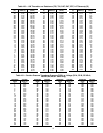
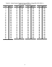
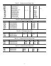
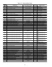
Temperatures
AIR.T
OAT Outside Air Temperature 30 minutes
Temperatures
AIR.T
RAT Return Air Temperature 3 minutes
Temperatures
AIR.T
SPT Space Temperature 3 minutes
Inputs
RSET
SP.RS Static Pressure Reset 30 minutes
Inputs
REL.H
OA.RH Outside Air Relative Humidity 30 minutes
Inputs
AIR.Q
OAQ Outside Air Quality 30 minutes