


166
APPENDIX C — VFD INFORMATION (cont)
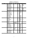
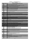
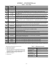
Table C — Fault Codes
FAULT
CODE
FAULT NAME
IN PANEL
DESCRIPTION AND RECOMMENDED CORRECTIVE ACTION
1 OVERCURRENT
Output current is excessive. Check for excessive motor load, insufficient acceleration time (parameters 2202 ACCELER TIME 1,
default 30 seconds), or faulty motor, motor cables or connections.
2 DC OVERVOLT
Intermediate circuit DC voltage is excessive. Check for static or transient over voltages in the input power supply, insufficient deceler-
ation time (parameters 2203 DECELER TIME 1, default 30 seconds), or undersized brake chopper (if present).
3 DEV OVERTEMP
Drive heat sink is overheated. Temperature is at or above 115 C (239 F). Check for fan failure, obstructions in the air flow, dirt or dust
coating on the heat sink, excessive ambient temperature, or excessive motor load.
4 SHORT CIRC Fault current. Check for short-circuit in the motor cable(s) or motor or supply disturbances.
5 OVERLOAD Inverter overload condition. The drive output current exceeds the ratings.
6 DC UNDERVOLT
Intermediate circuit DC voltage is not sufficient. Check for missing phase in the input power supply, blown fuse, or under voltage on
main circuit.
7 AI1 LOSS
Analog input 1 loss. Analog input value is less than AI1 FLT LIMIT (3021). Check source and connection for analog input and param-
eter settings for AI1 FLT LIMIT (3021) and 3001 AI<MIN FUNCTION.
8 AI2 LOSS
Analog input 2 loss. Analog input value is less than AI2 FLT LIMIT (3022). Check source and connection for analog input and param-
eter settings for AI2 FLT LIMIT (3022) and 3001 AI<MIN FUNCTION.
9 MOT OVERTEMP
Motor is too hot, as estimated by the drive. Check for overloaded motor. Adjust the parameters used for the estimate (3005 through
3009). Check the temperature sensors and Group 35 parameters.
10 PANEL LOSS
Panel communication is lost and either drive is in local control mode (the control panel displays LOC), or drive is in remote control
mode (REM) and is parameterized to accept start/stop, direction or reference from the control panel. To correct check the communi-
cation lines and connections. Check parameter 3002 PANEL COMM ERROR, parameters in Group 10: Command Inputs and Group
11:Reference Select (if drive operation is REM).
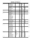
11 ID RUN FAIL The motor ID run was not completed successfully. Check motor connections.
12 MOTOR STALL
Motor or process stall. Motor is operating in the stall region. Check for excessive load or insufficient motor power. Check parameters
3010 through 3012.
13 RESERVED Not used.
14 EXT FAULT 1 Digital input defined to report first external fault is active. See parameter 3003 EXTERNAL FAULT 1.
15 EXT FAULT 2 Digital input defined to report second external fault is active. See parameter 3004 EXTERNAL FAULT 2.
16 EARTH FAULT
The load on the input power system is out of balance. Check for faults in the motor or motor cable. Verify that motor cable does not
exceed maximum specified length.
17 UNDERLOAD
Motor load is lower than expected. Check for disconnected load. Check parameters 3013 UNDERLOAD FUNCTION through 3015
UNDERLOAD CURVE.
18 THERM FAIL Internal fault. The thermistor measuring the internal temperature of the drive is open or shorted. Contact Carrier.
19 OPEX LINK Internal fault. A communication-related problem has been detected between the OMIO and OINT boards. Contact Carrier.
20 OPEX PWR Internal fault. Low voltage condition detected on the OINT board. Contact Carrier.
21 CURR MEAS Internal fault. Current measurement is out of range. Contact Carrier.
22 SUPPLY PHASE Ripple voltage in the DC link is too high. Check for missing main phase or blown fuse.
23 RESERVED Not used.
24 OVERSPEED
Motor speed is greater than 120% of the larger (in magnitude) of 2001 MINIMUM SPEED or 2002 MAXIMUM SPEED parameters.
Check parameter settings for 2001 and 2002. Check adequacy of motor braking torque. Check applicability of torque control. Check
brake chopper and resistor.
25 RESERVED Not used.
26 DRIVE ID Internal fault. Configuration block drive ID is not valid.
27 CONFIG FILE Internal configuration file has an error. Contact Carrier.
28 SERIAL 1 ERR
Field bus communication has timed out. Check fault setup (3018 COMM FAULT FUNC and 3019 COMM FAULT TIME). Check com-
munication settings (Group 51 or 53 as appropriate). Check for poor connections and/or noise on line.
29 EFB CON FILE Error in reading the configuration file for the field bus adapter.
30 FORCE TRIP Fault trip forced by the field bus. See the field bus reference literature.
31 EFB 1 Fault code reserved for the EFB protocol application. The meaning is protocol dependent.
32 EFB 2 Fault code reserved for the EFB protocol application. The meaning is protocol dependent.
33 EFB 3 Fault code reserved for the EFB protocol application. The meaning is protocol dependent.
34 MOTOR PHASE Fault in the motor circuit. One of the motor phases is lost. Check for motor fault, motor cable fault, thermal relay fault, or internal fault.
35 OUTP WIRING Error in power wiring suspected. Check that input power wired to drive output. Check for ground faults.
101-105 SYSTEM ERROR Error internal to the drive. Contact Carrier and report the error number.
201-206 SYSTEM ERROR Error internal to the drive. Contact Carrier and report the error number.
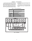
1000 PAR HZRPM
Parameter values are inconsistent. Check for any of the following:
2001 MINIMUM SPEED > 2002 MAXIMUM SPEED
2007 MINIMUM FREQ > 2008 MAXIMUM FREQ
2001 MINIMUM SPEED / 9908 MOTOR NOM SPEED is outside of the range: -128/+128
2002 MAXIMUM SPEED / 9908 MOTOR NOM SPEED is outside of the range: -128/+128
2007 MINIMUM FREQ / 9907 MOTOR NOM FREQ is outside of the range: - 128/+128
2008 MAXIMUM FREQ / 9907 MOTOR NOM FREQ is outside of the range: - 128/+128
1001 PAR PFA REFNG Parameter values are inconsistent. Check that 2007 MINIMUM FREQ is negative, when 8123 PFA ENABLE is active.
1002 PAR PFA IOCNF
Parameter values are inconsistent. The number of programmed PFA relays does not match with Interlock configuration, when 8123
PFA ENABLE is active. Check consistency of RELAY OUTPUT parameters 1401 through 1403, and 1410 through 1412. Check 8117
NR OF AUX MOTORS, 8118 AUTOCHANGE INTERV, and 8120 INTERLOCKS.
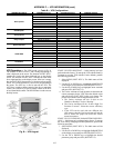
1003 PAR AI SCALE
Parameter values are inconsistent. Check that parameter 1301 AI 1 MIN > 1302 AI 1 MAX and that parameter 1304 AI 2 MIN > 1305
AI 2 MAX.
1004 PAR AO SCALE
Parameter values are inconsistent. Check that parameter 1504 AO 1 MIN > 1505 AO 1 MAX and that parameter 1510 AO 2 MIN >
1511 AO 2 MAX.
1005 PAR PCU 2
Parameter values for power control are inconsistent: Improper motor nominal kVA or motor nominal power. Check the following
parameters:
1.1 < (9906 MOTOR NOM CURR * 9905 MOTOR NOM VOLT * 1.73 / PN) < 2.6
Where: PN = 1000 * 9909 MOTOR NOM POWER (if units are kW) or PN = 746
* 9909 MOTOR NOM POWER (if units are HP, e.g., in US)
1006 PAR EXT RO
Parameter values are inconsistent. Check the extension relay module for connection and 1410 through 1412 RELAY OUTPUTS 4
through 6 have non-zero values.
1007 PAR FBUS
Parameter values are inconsistent. Check that a parameter is set for field bus control (e.g., 1001 EXT1 COMMANDS = 10 (COMM)),
but 9802 COMM PROT SEL = 0.
1008 PAR PFA MODE Parameter values are inconsistent. The 9904 MOTOR CTRL MODE must = 3 (SCALAR SPEED) when 8123 PFA ENABLE activated.
1009 PAR PCU 1
Parameter values for power control are inconsistent or improper motor nominal frequency or speed. Check for both of the following:
1 < (60 * 9907 MOTOR NOM FREQ / 9908 MOTOR NOM SPEED < 16
0.8 < 9908 MOTOR NOM SPEED / (120 * 9907 MOTOR NOM FREQ / Motor poles) < 0.992
1010
OVERRIDE/PFA
CONFLICT
Override mode is enabled and PFA is activated at the same time. This cannot be done because PFA interlocks cannot be observed in
the override mode.