


32
IQ.I.C
= 2 (IAQ Discrete Override) — If the user sets IQ.I.C
to 2 (IAQ Discrete Override), and Configuration
SW.LG
IAQ.L is set to OPEN, then an open switch reads low and a
closed switch reads high.
If the switch reads low, no action will be taken. If the switch
reads high, the economizer will immediately be commanded to
the IAQ Economizer Override Position. This can be set from 0
to 100% and can be found at Configuration
IAQ
AQ.SP
IQ.O.P.
FAN CONTROL FOR THE IAQ DISCRETE INPUT —
Under Configuration
IAQ
AQ.CF, the IQ.I.F (IAQ Dis-
crete Input Fan Configuration) must also be set. There are
three configurations for IQ.I.F. Select the configuration which
will be used for fan operation. This configuration allows the
user to decide (if the supply fan is not already running),
whether the IAQ discrete switch will start the fan, and in which
state of occupancy the fan will start.
IAQ ANALOG INPUT CONFIGURATION — This input is
an analog input located on the main base board (MBB). There
are 4 different functions for this input. The location of this con-
figuration is at Configuration
IAQ
AQ.CF
IQ.A.C.
The functions possible for IQ.A.C are:
• 0 = no IAQ analog input
• 1 = IAQ analog input
• 2 = IAQ analog input used to override to a set position
• 3 = 4 to 20 mA 0 to 100% economizer minimum position
control
• 4 = 0 to 10 kilo-ohms 0 to 100% economizer minimum
position control
Options 2, 3, and 4 are dedicated for third party control.
IQ.A.C
= 2 (IAQ Analog Input Used to Override) — Under
Configuration
IAQ
AQ.SP, set IQ.O.P (IAQ Economizer
Override Position). The IQ.O.P configuration is adjustable
from 0 to 100%. These configurations are also used in conjunc-
tion with Configuration
IAQ
AQ.CF
IQ.A.F (IAQ 4 to
20 mA Fan Configuration). There are three configurations for
IQ.A.F and they follow the same logic as for the discrete input.
This configuration allows the user to decide (if the supply fan is
not already running), if the IAQ Analog Minimum Position
Override input will start the fan, and in which state of occupan-
cy the fan will start.
If IQ.A.F is configured to request the supply fan, then
configurations D.F.ON and D.F.OF need to be set. These
configuration settings are located under Configuration
IAQ
AQ.SP and configure the fan override operation based
on the differential air quality (DAQ). If DAQ rises above
D.F.ON, the control will request the fan on until DAQ falls be-
low D.F.OF.
NOTE: If D.F.ON is configured below DAQ.H, the unit is in
occupied mode, and the fan was off, then DAQ rose above
D.F.ON and the fan came on, the economizer will go to the
economizer minimum position (EC.MN).
The 4 to 20 mA signal from the sensor wired to TB5-6 and
7 is scaled to an equivalent indoor CO
2
(IAQ) by the parame-
ters IQ.R.L and IQ.R.H located under the Configuration
IAQ
AQ.S.R menu. The parameters are defined such that
4 mA = IQ.R.L and 20 mA = IQ.R.H. When the differential air
quality DAQ (IAQ – OAQ.U) exceeds the DAQ.H set point
(Configuration
IAQ
AQ.SP menu) and the supply fan is
on, the economizer minimum vent position (Configuration
IAQ
DCV.C
EC.MN) is overridden and the damper is
moved to the IQ.P.O configuration. When the DAQ falls below
the DAQ.L set point (Configuration
IAQ
AQ.SP menu),
the economizer damper is moved back to the minimum vent
position (EC.MN).
NOTE: Configuration OAQ.U is used in the calculation of the
trip point for override and can be found under Configura-
tion
IAQ
AQ.SP.
IQ.A.C
= 3 (4 to 20 mA Damper Control) — This configura-
tion will provide full 4 to 20 mA remotely controlled analog in-
put for economizer minimum damper position. The 4 to 20 mA
signal is connected to terminals TB5-6 and 7. The input is
processed as 4 mA = 0% and 20 mA = 100%, thereby giving
complete range control of the effective minimum position.
The economizer sequences can be disabled by setting Con-
figuration
ECON
E.SEL to 0. Complete control of the
economizer damper position is then possible by using a 4 to
20 mA economizer minimum position control or a 0 to
10 kilo-ohm 0 to 100% economizer minimum position control
via configuration decisions at Configuration
IAQ
AQ.CF
IQ.A.C.
IQ.A.C
= 4 (10 Kilo-ohm Potentiometer Damper Control)
— This configuration will provide input for a 10 kilo-ohm lin-
ear potentiometer that acts as a remotely controlled analog in-
put for economizer minimum damper position. The input is
processed as 0 ohms = 0% and 10,000 ohms = 100%, thereby
giving complete range control of the effective minimum
position.
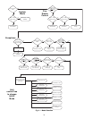
CONTROLS OPERATION
Modes —
The ComfortLink™ controls operate under a
hierarchy of command structure as defined by three essential
elements: the System mode, the HVAC mode and the Control
mode. The System mode is the top level mode that defines three
essential states for the control system: OFF, RUN and TEST.
The HVAC mode is the functional level underneath the
System mode which further defines the operation of the
control. The mode selection process is shown in Appendix D.
The Control mode is essentially the control type of the unit
(Configuration
UNIT
C.TYP). This defines from where
the control looks to establish a cooling or heating mode and
whether 2 stages or multiple stages of cooling capacity opera-
tion are controlled.
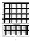
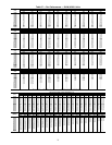
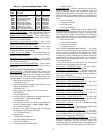
Furthermore, there are a number of modes which operate
concurrently when the unit is running. The operating modes of
the control are located at the local displays under Operating
Modes. See Table 42.
Currently Occupied (
OCC) — This variable displays the cur-
rent occupied state of the unit.
Timed Override in Effect (
T.OVR) — This variable displays
if the state of occupancy is currently occupied due to an
override.
DCV Resetting Minimum Position (
DCV) — This variable
displays if the economizer position has been lowered from its
maximum vent position.
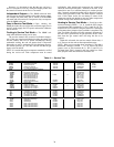
IQ.I.F = 0 Minimum Position Override Switch input
will not start fan
IQ.I.F = 1 Minimum Position Override Switch input
will start fan in occupied mode only
IQ.I.F = 2 Minimum Position Override Switch input
will start fan in both occupied and unoccu-
pied modes
IQ.A.F = 0 IAQ analog sensor input cannot start the
supply fan
IQ.A.F = 1 IAQ analog sensor input can start the supply
fan in occupied mode only
IQ.A.F = 2 IAQ analog sensor input can start the supply
fan in both occupied and unoccupied modes