


33
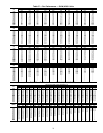
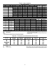
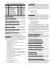
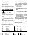
Table 42 — Operating Modes Display Table
Supply Air Reset (
SA.R) — This variable displays if the sup-
ply air reset is currently active. This applies to cooling only.
Demand Limit in Effect (
DMD.L) — This variable displays
if the mechanical cooling capacity is currently being limited or
reduced by an outside third party.
Temperature Compensated Start (
T.C.ST) — This variable
displays if Heating or Cooling has been initiated before the
occupied period to pre-condition the space.
IAQ Pre-Occupancy Purge Active (
IAQ.P) — This variable
displays if the economizer is open and the fan is on to pre-
ventilate the building before occupancy.
Linkage Active CCN (
LINK) — This variable displays if a
linkage master in a zoning system has established “linkage”
with this air source (rooftop).
Mechanical Cooling Locked Out (
LOCK) — This variable
displays if mechanical cooling is currently being locked due to
low outside air temperature.
HVAC Mode Numerical Form (
H.NUM) — This is a numer-
ical representation of the HVAC modes which may be read via
a point read.
SYSTEM MODES (Operating Modes
SYS.M)
System Mode Off
— When the system mode is OFF, all out-
puts are to be shut down and no machine control is possible.
The following list displays the text assigned to the System
Mode when in the OFF mode and the conditions that may
cause this mode are checked in the following hierarchal order:
1. Wake up timer on a power reset.
(“Initializing System ...”)
2. System in the process of shutting down compressors and
waiting for timeguards to expire.
(“Shutting Down ...”)
3. Factory shut down (internal factory control level —
SHUTDOWN).
(“Factory Shut Down”)
4. Unit stop (software application level variable that acts as
a hard shut down — Service Test
STOP).
(“Local Machine Stop”)
5. Fire shut down (traumatic fire shutdown condition based
on the Fire Shutdown Input — Inputs
FIRE
FSD).
(“Fire-Shutdown Mode”)
6. Emergency stop, which is forced over the CCN through
the Emergency Stop Variable (EMSTOP).
(“CCN Emergency Stop”)
7. Startup delay.
(“Startup delay = 0-900 secs”)
8. Service test ending transition timer.
(“Service Test Ending”)
9. Unexplained internal software failure.
(“Internal Failure”)
System Mode Test
— When the system mode is Test, the con-
trol is limited to the Test mode and is controllable via the local
displays (scrolling marquee and Navigator™ display) or
through the factory service test control. The System Test
modes are Factory Test Enabled and Service Test Enabled. See
the Service Test Mode section for details on test control in this
mode.
1. Factory Test mode
(“Factory test enabled”)
2. Service Test mode
(“Service test enabled”)
System Mode Run
— When the system mode is Run, the soft-
ware application in the control is free to run the HVAC control
routines by which cooling, heating, IAQ, etc., is possible. There
are two possible text displays for this mode, one is normal run
mode and the other occurs if one of the following fire-smoke
modes is present: smoke purge, pressurization or evacuation.
1. Normal run time state
(“Unit Operation Enabled”)
2. Fire-Smoke control mode
(“Fire-Smoke Control”)
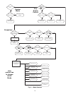
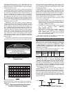
HVAC MODES (Operating Mode
HVAC) — The system
mode must be selected before the unit controls can select the
HVAC mode of the rooftop unit. The selection of an HVAC
mode is based on a hierarchal decision making process. Certain
overrides may interfere with this process and the normal tem-
perature/humidity control operation of the unit. The decision
making process that determines the HVAC mode is shown in
Fig. 4 and Appendix D.
Each HVAC Mode is described below. The HVAC mode
number is shown in parenthesis after the mode.
HVAC Mode — STARTING UP (0)
— The unit is transi-
tioning from the OFF mode to a different mode.
HVAC Mode — DISABLED (1)
— The unit is shut down
due to a software command disable through the scrolling mar-
quee, a CCN emergency stop command, a service test end, or a
control-type change delay.
HVAC Mode — SHUTTING DOWN (2)
— The unit is tran-
sitioning from a mode to the OFF mode.
HVAC Mode — SOFTSTOP REQUEST (3)
— The unit is
off due to a soft stop request from the control.
HVAC Mode — REM SW.DISABLE (4)
— The unit is off
due to the remote switch.
HVAC Mode — FAN STATUS FAIL (5)
— The unit is off
due to failure of the fan status switch.
HVAC Mode — STATIC PRESSURE FAIL (6)
— The unit is
off due to failure of the static pressure sensor.
HVAC Mode — COMP.STUCK ON (7)
— The unit is shut
down because there is an indication that a compressor is run-
ning even though it has been commanded off.
HVAC Mode — OFF (8)
— The unit is off and no operating
modes are active.
HVAC Mode — TEST
(9) — The unit is in the self test mode
which is entered through the Service Test menu.
HVAC Mode — TEMPERING VENT
(10) — The econo-
mizer is at minimum vent position but the supply-air tempera-
ture has dropped below the tempering vent set point. Staged
gas heat is used to temper the ventilation air.
HVAC Mode — TEMPERING LOCOOL
(11) — The econ-
omizer is at minimum vent position but the combination of the
outside-air temperature and the economizer position has
dropped the supply-air temperature below the tempering cool
set point. Staged gas heat is used to temper the ventilation air.
ITEM EXPANSION RANGE CCN POINT
SYS.M ascii string n/a
HVAC ascii string n/a
CTRL ascii string n/a
MODE MODES CONTROLLING UNIT
OCC Currently Occupied ON/OFF MODEOCCP
T.OVR Timed Override in Effect ON/OFF MODETOVR
DCV DCV Resetting Min Pos ON/OFF MODEADCV
SA.R Supply Air Reset ON/OFF MODESARS
DMD.L Demand Limit in Effect ON/OFF MODEDMLT
T.C.ST Temp.Compensated Start ON/OFF MODETCST
IAQ.P IAQ Pre-Occ Purge Active ON/OFF MODEIQPG
LINK Linkage Active — CCN ON/OFF MODELINK
LOCK Mech.Cooling Locked Out ON/OFF MODELOCK
H.NUM HVAC Mode Numerical Form number MODEHVAC