


124
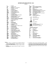
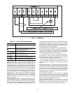
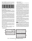
BOARD ADDRESSES — Each board in the system has an
address. The MBB has a default address of 1 but it does have
an instance jumper that should be set to 1 as shown in Fig. 26.
For the other boards in the system there is a 4-dip switch head-
er on each board that should be set as shown below.
0 = On; 1 = Off
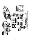
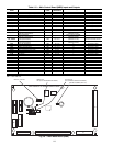
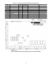
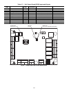
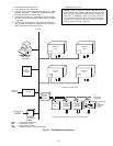
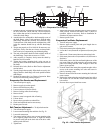
FIELD CONNECTION TERMINAL STRIPS — Field con-
nection terminal strips are located in the main control box. See
Fig. 32 and Table 122.
Accessory Control Components — In addition to
the factory-installed options, the units can also be equipped
with several field-installed accessories that expand the control
features of the unit. The following hardware components can
be used as accessories.
ROOM THERMOSTATS (48/50AJ,AW,A2,A4 UNITS
ONLY) — The ComfortLink™ controls support a conven-
tional electro-mechanical or electronic thermostat that uses the
Y1, Y2, W1, W2, and G signals. The control also supports an
additional input for an occupied/unoccupied command that is
available on some new thermostats. The ComfortLink controls
can be configured to run with multiple stages of capacity which
allows up to 6 stages of capacity. Although the unit can be con-
figured for normal 2-stage control, it is recommended that the
multi-stage control be used. The room thermostat is connected
to TB4.
SPACE SENSOR — The ComfortLink controls support the
use of space temperature sensors. The T55 and T56 sensors
and CCN communicating T58 room sensor can be used. The
T55 and T56 sensors are connected to TB5 terminal 3, 4, and 5.
The T58 sensor is connected to the CCN connections on TB3.
When a T55, T56, or T58 sensor is used, the user must install
the red jumpers from R to W1, and W2 on TB4 for the heat
function to work correctly.
SPACE CO
2
SENSORS — The ComfortLink controls also
support a CO
2
IAQ sensor that can be located in the space for
use in demand ventilation. The sensor must be a 4 to 20 mA
sensor and should be connected to TB5 terminal 6 and 7. See
Fig. 33 for sensor wiring.
ECONOMIZER HUMIDITY CHANGEOVER SEN-
SORS — The ComfortLink controls support 5 different
changeover schemes for the economizer. These are:
• outdoor air dry bulb
• differential dry bulb
• outdoor air enthalpy curves
• differential enthalpy
• custom curves (a combination of an enthalpy/dewpoint
curve and a dry bulb curve).
The units are equipped as standard with an outside air and
return air dry bulb sensor which supports the dry bulb change-
over methods. If the other methods are to be used, then a field-
installed humidity sensor must be installed for outdoor air en-
thalpy and customer curve control and two humidity sensors
must be installed for differential enthalpy. Installation holes are
pre-drilled and wire harnesses are installed in every unit for
connection of the humidity sensors. The ComfortLink controls
convert the measured humidity into enthalpy, dewpoint, and
the humidity changeover curves.
MOTORMASTER
®
V CONTROL — For operation below
32 F when an economizer is not used, the units can be equipped
with an accessory Motormaster V control, which controls the
speed of the stage 1 condenser fans. The Motormaster V control
is a 3-phase inverter that controls the speed of the fans based on
a pressure transducer connected to the liquid line. On 48/
50A020-035 units, one fan will be controlled. On 48/50A036-
060 units, two fans will be controlled. For units equipped with
an economizer, there should not be a need for this control be-
cause the economizer can provide free cooling using outside air,
which will be significantly lower in operating cost.
The accessory Motormaster V speed control is a completely
self-contained control and is not controlled by the unit’s
ComfortLink controller. On 48/50A051 and 060 units with 6
fan motors, the Motormaster control configuration (M.M.)
must be set to YES. See page 39.
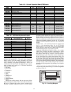
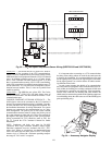
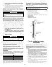
ACCESSORY NAVIGATOR™ DISPLAY — The accesso-
ry handheld Navigator display can be used with the 48/50A se-
ries units. See Fig. 34. The Navigator display operates the same
way as the scrolling marquee device. The ECB1 and ECB2
boards contain a second LEN port (J3 connection) than can be
used with the handheld Navigator display.
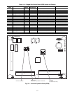
CONTROL MODULE COMMUNICATIONS
Red LED
— Proper operation of the control boards can be
visually checked by looking at the red status LEDs as shown on
Fig. 26-29. When operating correctly, the red status LEDs
should blink in unison at a rate of once every 2 seconds. If the
red LEDs are not blinking in unison, verify that correct power is
being supplied to all modules. Also, be sure that the main base
board is supplied with the current software. If necessary, reload
current software. If the problem still persists, replace the MBB.
A board LED that is lit continuously or blinking at a rate of once
per second or faster indicates that the board should be replaced.
BOARD SW1 SW2 SW3 SW4
ECB10000
ECB21000
SCB0000
CEM0000
13579111315
246810121416
12345678
R Y1Y2W1W2G C X
13579111315
246810121416
TB5
TB6
TB3
TB4
C
LEN
CCN
CCN
+
-
GRD
Fig. 32 — Field Connection Terminal Strips (Main Control Box)
A48-7081