


4
System diagnostics are enhanced by the use of multiple
external sensors for air temperatures, air pressures, refrigerant
temperatures, and refrigerant pressures. Unit-mounted actua-
tors provide digital feedback data to the unit control.
The ComfortLink control system is fully communicating
and cable-ready for connection to the Carrier Comfort Net-
work
®
(CCN) building management system. The control pro-
vides high-speed communications for remote monitoring via
the Internet. Multiple units can be linked together (and to other
ComfortLink control equipped units) using a 3-wire communi-
cation bus.
The ComfortLink control system is easy to access through
the use of a unit-mounted display module. There is no need to
bring a separate computer to this unit for start-up. Access to
control menus is simplified by the ability to quickly select from
11 menus. A scrolling readout provides detailed explanations
of control information. Only four, large, easy-to-use buttons are
required to maneuver through the entire controls menu.
For added service flexibility, an accessory hand-held
Navigator module is also available. This portable device has an
extended communication cable that can be plugged into the
unit’s communication network either at the main control box or
at the opposite end of the unit, at a remote modular plug. The
Navigator display provides the same menu structure, control
access and display data as is available at the unit-mounted
scrolling marquee display.
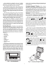
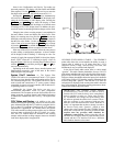
Scrolling Marquee — This device is the standard inter-
face used to access the control information, read sensor values,
and test the unit. The scrolling marquee is located in the main
control box. The scrolling marquee display is a 4-key, 4-char-
acter LED (light-emitting diode) display module. The display
also contains an Alarm Status LED. See Fig. 1. The display is
easy to operate using 4 buttons and a group of 11 LEDs that in-
dicate the following menu structures, referred to as modes (see
Appendix A):
• Run Status
• Service Test
• Temperatures
•Pressures
• Set points
• Inputs
• Outputs
• Configuration
• Timeclock
• Operating Modes
•Alarms
Through the scrolling marquee, the user can access all of the
inputs and outputs to check on their values and status, config-
ure operating parameters plus evaluate the current decision sta-
tus for operating modes. Because the A Series units are
equipped with suction pressure and saturated condensing
temperature transducers, the scrolling marquee can also display
refrigerant circuit pressures typically obtained from service
gages. The control also includes an alarm history which can be
accessed from the display. In addition, through the scrolling
marquee, the user can access a built-in test routine that can be
used at start-up commissioning to diagnose operational prob-
lems with the unit.
Accessory Navigator™ Display — The accessory
hand-held Navigator display can be used with the A Series
units. See Fig. 2. The Navigator display operates the same way
as the scrolling marquee device. The Navigator display is
plugged into the RJ-14 (LEN) jack in the main control box on
the COMM board. The Navigator display can also be plugged
into the RJ-14 jack located on the ECB (economizer control
board) located in the auxiliary control box.
Operation — All units are shipped from the factory with
the scrolling marquee display, which is located in the main con-
trol box. See Fig. 1. In addition, the ComfortLink™ controls
also support the use of the handheld Navigator display.
Both displays provide the user with an interface to the
ComfortLink control system. The displays have and
arrow keys, an key and an key. These
keys are used to navigate through the different modes of the
display structure. The Navigator and the scrolling marquee dis-
plays operate in the same manner, except that the Navigator
display has multiple lines of display and the scrolling marquee
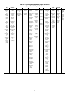
has a single line. All further discussions and examples in this
document will be based on the scrolling marquee display. See
Table 2 for the menu structure.
The four keys are used to navigate through the display
structure, which is organized in a tiered mode structure. If the
buttons have not been used for a period, the display will default
to the AUTO VIEW display category as shown under the RUN
STATUS category. To show the top-level display, press the
key until a blank display is shown. Then
use the and arrow keys to scroll through the top-level
categories (modes). These are listed in Appendix A and will be
indicated on the scrolling marquee by the LED next to each
mode listed on the face of the display.
When a specific mode or sub-mode is located, push the
key to enter the mode. Depending on the mode, there
may be additional tiers. Continue to use the and keys
and the keys until the desired display item is found.
At any time, the user can move back a mode level by pressing
the key. Once an item has been selected the display
will flash showing the item, followed by the item value and
then followed by the item units (if any).
ESCAPE
ENTER
ESCAPE
ENTER
ENTER
ESCAPE
Run Status
Service Test
Temperature
Pressures
Setpoints
Inputs
Outputs
Configuration
Time Clock
Operating Modes
Alarms
Alarm Status
ENTER
MODE
ESCAPE
Fig. 1 — Scrolling Marquee
A30-2239
Ru
n Sta
tu
s
S
e
rv
ice
Te
s
t
T
em
p
era
ture
s
P
res
s
ure
s
S
e
tpo
in
ts
In
pu
ts
O
utp
uts
C
on
fig
u
ra
tion
T
im
e
Clo
ck
O
p
er
ating
M
od
es
A
la
rm
s
E
N
T
E
R
E
S
C
M
O
D
E
Ala
rm
St a
tus
T
IM
E
E
W
T
L
W
T
S
E
T
P
1
2
.
5
8
5
4
.
6
F
4
4
.1
F
4
4
.
0
F
N
A
V
I
G
A
T
O
R
C
o
m
f
o
r
t
L
in
k
Fig. 2 — Accessory Navigator Display
30-650