


38
out a LOW COOL or a HIGH COOL mode and maintain a
low or high cool supply air set point.
• C.TYP = 6 (SPT-2 STG)
This configuration will force the control to monitor the
space temperature sensor to make a determination of mode
and allow two stages of cooling.
MACHINE DEPENDENT CONFIGURATIONS — Some
configurations are linked to the physical unit and must not be
changed. The configurations are provided in case a field re-
placement of a board occurs and the settings are not preserved
by the download process of the new software. The following
configurations apply to all machine control types (C.TYP) ex-
cept 4 and 6. These configurations are located at the local dis-
play under Configuration
UNIT. See Table 44.
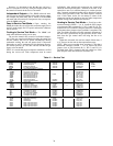
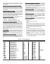
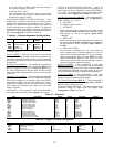
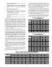
Table 44 — Machine Dependent Configurations
*Dependent on unit.
Unit Size (SIZE) — There are several unit sizes (tons) for the
A Series control. Make sure this configuration matches the size
called out by the model number of the unit. This is important as
the cooling stage tables are directly determined based on this
configuration.
Refrigerant Type (
RFG.T) — This configuration specifies the
type of refrigerant used in the unit. Configuration RFG.T is set
to 0 if the refrigerant used is R-22. Configuration RFG.T is set
to 1 if the refrigerant used is R-410A. Make sure this configu-
ration matches the refrigerant called out by the model number
of the unit.
Condenser Type (
CND.T) — This configuration specifies the
type of condenser installed in the unit. Configuration CND.T is
set to 0 if the condenser is a round tube, plate fin coil (RTPF).
Configuration CND.T is set to 1 if the condenser is a micro-
channel heat exchanger coil (MCHX). Make sure this configu-
ration matches the condenser type called out by the model
number of the unit.
SET POINTS — The set points for both cooling and heating
are located at the local display under Setpoints. See Table 45.
SUPPLY AIR RESET CONFIGURATION — Supply Air
Reset can be used to modify the current cooling supply air set
point. Supply Air Reset is applicable to control types, C.TYP =
1,2,3, and 5. The configurations for reset can be found at the
local display under Configuration
EDT.R. See Table 46.
EDT Reset Configuration (
RS.CF) — This configuration ap-
plies to several machine control types (Configuration
UNIT
C.TYP = 1,2,3, and 5).
• 0 = NO RESET
No supply air reset is in effect
•1 = SPT RESET
Space temperature will be used as the reset control variable
along with both RTIO and LIMT in the calculation of the
final amount of reset to be applied (Inputs
RSET
SA.S.R).
• 2 = RAT RESET
Return-air temperature will be used as the reset control vari-
able along with both RTIO and LIMT in the calculation of
the final amount of reset to be applied (Inputs
RSET
SA.S.R).
• 3 = 3RD PARTY RESET
The reset value is determined by a 4 to 20 mA third party
input. An input of 4 mA would correspond to 0º F reset. An
input of 20 mA would correspond to 20º F reset. Configur-
ing the control for this option will cause RES.S to become
enabled automatically with the CEM board. To avoid
alarms make sure the CEM board and third party input are
connected first before enabling this option.
Reset Ratio (
RTIO) — This configuration is used when
RS.CF is set to 1 or 2. For every degree that the controlling
temperature (space/return) falls below the occupied cooling set
point (OCSP), the calculated value of the supply air reset will
rise by the number of degrees as specified by this parameter.
Reset Limit (
LIMT) — This configuration is used when
RS.CF is set to 1 or 2. This configuration places a clamp on the
amount of supply air reset that can be applied.
EDT 4-20 mA Reset Input (
RES.S) — This configuration is
automatically enabled when Configuration
EDT.R
RS.CF is set to 3 (third party reset).
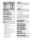
COOLING CONFIGURATION — Relevant configurations for
mechanical cooling are located at the local display under
Configuration
COOL. See Table 47.
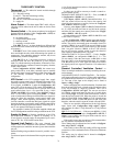
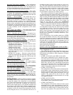
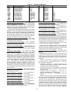
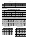
Table 45 — Setpoints
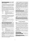
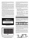
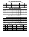
Table 46 — Supply Air Reset Configuration
ITEM EXPANSION RANGE
CCN
POINT
DEFAULTS
UNIT UNIT CONFIGURATION
SIZE Unit Size (20-60) 20-60 UNITSIZE *
RFG.T REFRIG 0-1 REFRIG_T *
CND.T CND HX TYP 0-1 COILTYPE *
ITEM EXPANSION RANGE UNITS CCN POINT DEFAULT
OHSP Occupied Heat Setpoint 40-99 dF OHSP 68
OCSP Occupied Cool Setpoint 40-99 dF OCSP 75
UHSP Unoccupied Heat Setpoint 40-99 dF UHSP 55
UCSP Unoccupied Cool Setpoint 40-99 dF UCSP 90
GAP Heat-Cool Setpoint Gap 2-10 ^F HCSP_GAP 5
V. C.ON VAV Occ. Cool On Delta 0-25 ^F VAVOCON 3.5
V. C.OF VAV Occ. Cool Off Delta 1-25 ^F VAVOCOFF 2
SASP Supply Air Setpoint 45-75 dF SASP 55
SA.HI Supply Air Setpoint Hi 45-75 dF SASP_HI 55
SA.LO Supply Air Setpoint Lo 45-75 dF SASP_LO 60
SA.HT Heating Supply Air Setpt 90-145 dF SASPHEAT 85
T.PRG Tempering Purge SASP –20-80 dF TEMPPURG 50
T.CL Tempering in Cool SASP 5-75 dF TEMPCOOL 5
T.V.OC Tempering Vent Occ SASP –20-80 dF TEMPVOCC 65
T.V.UN Tempering Vent Unocc. SASP –20-80 dF TEMPVUNC 50
ITEM EXPANSION RANGE UNITS CCN POINT DEFAULT
EDT.R EVAP.DISCHRGE TEMP RESET
RS.CF EDT Reset Configuration 0 - 3 EDRSTCFG 0
RTIO Reset Ratio 0 - 10 RTIO 2
LIMT Reset Limit 0 - 20 ^F LIMT 10
RES.S EDT 4-20 ma Reset Input Enable/Disable EDTRSENS Disable