


57
HVAC mode = “Tempering LoCool”
HVAC mode = “Tempering HiCool”
The decision making/selection process for the tempering
trip set point is as follows:
• If an HVAC cool mode is in effect, then the vent trip point is
T.CL.
• If in a pre-occupied purge mode (Operating Modes
MODE
IAQ.P=ON), then the trip point is T.P RG.
• If in an occupied mode (Operating Modes
MODE
IAQ.P=ON), then the trip point is T.V.OC.
• For all other cases, the trip point is T.V.UN.
NOTE: The unoccupied economizer free cooling mode does
not qualify as a HVAC cool mode as it is an energy saving
feature and has its own OAT lockout already. The unoccupied
free cooling mode (HVAC mode = Unocc. Free Cool) will
override any unoccupied vent mode from triggering a temper-
ing mode.
If OAT is above the chosen tempering set point, tempering
will not be allowed. Additionally, tempering mode is locked
out if any stages of mechanical cooling are present.
A minimum amount of time must pass before calling out
any tempering mode. In effect, the EDT must fall below
the trip point value –1° F continuously for a minimum of
2 minutes. Also, at the end of a mechanical cooling cycle, there
must be a minimum 10 minutes of delay allowed before con-
sidering tempering during vent mode in order to allow any
residual cooling to dissipate from the evaporator coil.
If the above conditions are met, the algorithm is free to
select the tempering mode (MODETEMP). If a tempering
mode becomes active, the modulating heat source (staged gas)
will attempt to maintain leaving-air temperature (LAT) at the
tempering set point used to trigger the tempering mode. The
technique for modulation of set point for staged gas and
hydronic heat is the same as in a heat mode. More information
regarding the operation of heating can be referenced in the
Heating Control section.
Recovery from a tempering mode (MODETEMP) will
occur when the EDT rises above the trip point. On any change
in HVACMODE, the tempering routine will re-assess the
tempering set point which may cause the control to continue or
exit tempering mode.
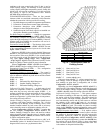
Static Pressure Control — Variable air volume (VAV)
air-conditioning systems must provide varying amounts of air
to the conditioned space. As air terminals downstream of the
unit modulate their flows, the unit must maintain control over
the duct static pressure in order to accommodate the needs of
the terminals and meet the varying combined airflow require-
ment.
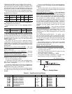
A 48/50AK,AY,A3,A5 unit equipped with a duct pressure
control system is provided with a variable frequency drive
(VFD) for the supply fan. The speed of the fan can be con-
trolled directly by the ComfortLink™ controls. A transducer is
used to measure duct static pressure. The signal from the trans-
ducer is received by the ECB-2 board and is then used in a PID
control routine that outputs a 4 to 20 mA signal to the VFD.
Generally, only VAV systems utilize static pressure control.
It is required because as the system VAV terminals modulate
closed when less air is required, there must be a means of
controlling airflow from the unit, thereby effectively prevent-
ing overpressurization and its accompanying problems.
The three most fundamental configurations for most appli-
cations are Configuration
SP
SP.CF, which is the static
pressure control type, Configuration
SP
SP.S, used to
enable the static pressure sensor, and Configuration
SP
SP.SP, the static pressure set point to be maintained.
OPERATION — On units equipped with a VFD and a proper
static pressure sensor, when SP.CF, SP.S and SP.SP are config-
ured, a PID routine periodically measures the duct static
pressure and calculates the error from set point. This error is
simply the duct static pressure set point minus the measured
duct static pressure. The error becomes the basis for the propor-
tional term of the PID. The routine also calculates the integral
of the error over time, and the derivative (rate of change) of the
error. A value is calculated as a result of this PID routine, and
this value is then used to create an output signal used to adjust
the VFD to maintain the static pressure set point.
Static pressure reset is the ability to force a lowering of the
static pressure set point through an external control signal.
The unit controls support this in two separate ways, through a 4
to 20 mA signal input wired to the unit’s isolator board input
terminals (third party control) or via CCN.
When employing the CCN, this feature uses the communi-
cations capabilities of VAV systems with ComfortID™ termi-
nals under linkage. The system dynamically determines and
maintains an optimal duct static pressure set point based on
the actual load conditions in the space. This can result in a
significant reduction in required fan energy by lowering the set
point to only the level required to maintain adequate airflow
throughout the system.
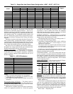
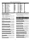
SETTING UP THE SYSTEM — The options for static
pressure control are found under the Local Display Mode
Configuration
SP. See Table 75.
Static Pressure Configuration (
SP.CF) — This variable is
used to configure the use of ComfortLink™ controls for static
pressure control. There are the following options:
0 (None)
— There will be no static pressure control by Com-
fortLink controls. This setting would be used for a constant
volume (CV) application when static pressure control is not re-
quired or for a VAV application if there will be third-party con-
trol of the VFD. In this latter case, a suitable means of control
must be field installed.
Additionally, SP.CF must be set to 0 (None) when a unit is
equipped with optional VFD bypass and is operating in Bypass
mode. Failure to change this configuration in Bypass mode will
result in the indoor fan motor running continuously.
1 (VFD Control)
— This will enable the use of ComfortLink
controls for static pressure control via a supply fan VFD.
Static Pressure Fan Control? (
SP.FN) — This is automatical-
ly set to Yes when SP.CF = 1. When the user would like the 4
to 20 mA output to energize the VFD, as opposed to the fan re-
lay, SP.FN may be set to Yes when SP.CF = 0. When the con-
trol turns the fan ON, the control will send the SP.MX value of
the 4 to 20 mA signal to the third party VFD control.
Additionally, SP.FN must be set to NO when the unit is
equipped with optional VFD bypass and is operating in Bypass
mode. Failure to change this configuration in bypass mode will
result in the indoor fan motor running continuously.
Static Pressure Sensor (
SP.S) — This variable enables the use
of a supply duct static pressure sensor. This must be enabled to
use ComfortLink controls for static pressure control. If using a
third-party control for the VFD, this should be disabled.
Static Pressure Low Range (
SP.LO) — This is the minimum
static pressure that the sensor will measure. For most sensors
this will be 0 in. wg. The ComfortLink controls will map this
value to a 4 mA sensor input.
Static Pressure High Range (
SP.HI) — This is the maximum
static pressure that the sensor will measure. Commonly this
will be 5 in. wg. The ComfortLink controls will map this value
to a 20 mA sensor input.
CAUTION
Failure to correctly configure SP.CF and SP.FN when
operating in VFD Bypass mode will result in the indoor fan
motor running continuously. Damage to unit could result.