


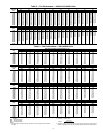
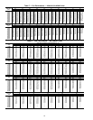

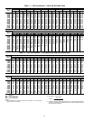
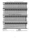

7
START-UP
Unit Preparation —
Check that unit has been installed in
accordance with the installation instructions and applicable
codes.
Unit Setup — Make sure that the economizer hoods have
been installed and that the outdoor filters are properly installed.
Internal Wiring — Ensure that all electrical connections
in the control box are tightened as required. If the unit has
staged gas heat make sure that the leaving air temperature
(LAT) sensors have been routed to the supply ducts as required.
Accessory Installation — Check to make sure that all
accessories including space thermostats and sensors have been
installed and wired as required by the instructions and unit
wiring diagrams.
Crankcase Heaters — Crankcase heaters are energized
as long as there is power to the unit, except when the compres-
sors are running.
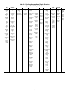
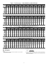
Evaporator Fan — Fan belt and fixed pulleys are factory-
installed. See Tables 3-38 for fan performance. Remove tape
from fan pulley, and be sure that fans rotate in the proper direc-
tion. See Table 39 for motor limitations. See Tables 40A and
40B for air quantity limits. Static pressure drop for power
exhaust is negligible. To alter fan performance, see Evaporator
Fan Performance Adjustment section on page 130.
Controls — Use the following steps for the controls:
1. Set any control configurations that are required (field-
installed accessories, etc.). The unit is factory configured
for all appropriate factory-installed options.
2. Enter unit set points. The unit is shipped with the set point
default values. If a different set point is required use the
scrolling marquee, Navigator™ accessory or Service
Tool software to change the configuration valves.
3. If the internal unit schedules are going to be used config-
ure the Occupancy schedule.
4. Verify that the control time periods programmed meet
current requirements.
5. Using Service Test mode, verify operation of all major
components.
6. If the unit is a VAV unit make sure to configure the VFD
static pressure set point using the display. To checkout the
VFD use the VFD instructions shipped with the unit.
Gas Heat — Verify gas pressure before turning on gas heat
as follows:
1. Turn off field-supplied manual gas stop, located external
to the unit.
2. Connect pressure gages to supply gas tap, located at field-
supplied manual shutoff valves.
3. Connect pressure gages to manifold pressure tap on unit
gas valve.
4. Supply gas pressure must not exceed 13.5 in. wg. Check
pressure at field-supplied shut-off valve.
5. Turn on manual gas stop and initiate a heating demand.
Jumper R to W1 in the control box to initiate heat.
6. Use the Service Test procedure to verify heat operation.
7. After the unit has run for several minutes, verify that
incoming pressure is 6.0 in. wg or greater and that the
manifold pressure is 3.5 in wg. If manifold pressure must
be adjusted refer to Gas Valve Adjustment section.
IMPORTANT: Do not attempt to start unit, even
momentarily, until all items on the Start-Up Checklist
and the following steps have been completed.
IMPORTANT: Unit power must be on for 24 hrs prior
to start-up of compressors. Otherwise damage to com-
pressors may result.
IMPORTANT: The unit is shipped with the unit control
disabled. To enable the control, set Local Machine Disable
(Service Test
STOP) to No.