


37
Reset MAT Table Entries? (
MAT.R) — This configuration
allows the user to reset the internally stored MAT learned con-
figuration data back to the default values. The defaults are set
to a linear relationship between the economizer damper posi-
tion and OAT and RAT in the calculation of MAT.
MAT Outside Air Position Default (
MAT.D) — This config-
uration is used to calculate MAT when the economizer option
is disabled. The configuration is adjustable from 0 to 100%
outside air. This defines the fixed ventilation position that will
be used to correctly calculate MAT.
Altitude……..In Feet: (
ALTI) — The control does not in-
clude a barometric pressure sensor to determine altitude. The
altitude must be defined the calculation of enthalpy and cfm.
The altitude parameter is used to set up a default barometric
pressure for use with calculations. The effect of barometric
pressure in these calculations is not great, but could have an ef-
fect depending on the installed elevation of the unit. If the unit
is installed at a particularly high altitude and enthalpy or cfm
are being calculated, set this configuration to the current
elevation.
Start Up Delay Time (
DLAY) — This option delays the unit
from operating after a power reset. The configuration may be
adjusted from 0 to 900 seconds of delay.
TSTAT — Both Heat and Cool (
STAT) — This option, if en-
abled, allows both heating and cooling requests to be made at
the same time. If the unit is configured for staged gas heat, and
if a cooling request is initiated (Y1 or Y2), then W1 initiates re-
heat and W2 initiates dehumidification.
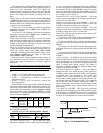
Auxiliary Relay Configuration (
AUX.R) — This option con-
figures the auxiliary relay on the MBB (RLY11). The function
of this relay is configurable in the following ways:
• AUX.R = 0 (Alarm Output) — The relay is used for remote
annunciation of an alarm state.
• AUX.R = 1 (Dehum-Reheat) — The relay is used as a dehu-
midification/reheat output.
• AUX.R = 2 (Occup. State) — The relay is used to reflect
occupancy. When the control is in occupied mode, the relay
will be ON. When the control is in unoccupied mode, the
relay will be OFF.
• AUX.R = 3 (S. Fan State) — The relay is used to reflect the
supply fan commanded state. When the supply fan is on, the
relay will be ON. When the supply fan is off, the relay will
be OFF.
Space Temp Sensor (
SPT.S) — If a space temperature sensor
is installed, this configuration should be enabled.
Space Temp Offset Sensor (
SP.O.S) — If a space tempera-
ture sensor with a space temperature offset slider is installed
(T56), this configuration should be enabled.
Space Temp Offset Range (
SP.O.R) — If a space tempera-
ture offset sensor is installed, it is possible to configure the
range of the slider by adjusting this range configuration.
Return RH Sensor (
RRH.S) — If a return air relative humidi-
ty sensor is installed, this configuration should be enabled.
Filter Status Switch Enabled? (
FLT.S) — If a filter status
switch is installed, enable this configuration to begin the moni-
toring of the filter status input (Inputs
GEN.I
FLT.S). See
the Dirty Filter Switch section for more details on installation
and operation.
Cooling Control — When mechanical cooling is required,
the A Series ComfortLink™ control system has the capability
to control the staging of the compressors in several different
ways. Three scroll compressors are used on sizes 020 to 027
and four on sizes 030 to 060. In addition, the ComfortLink
control system supports the use of an optional minimum load
hot gas bypass valve (MLV) that is directly controlled by the
ComfortLink control system. This provides an additional stage
of capacity as well as low load coil freeze protection. The con-
trol also integrates the use of an economizer with the use of
mechanical cooling to allow for the greatest use of free cool-
ing. When both mechanical cooling and the economizer are
being used, the control will use the economizer to provide bet-
ter temperature control and limit the cycling of the compres-
sors. The control also checks on various other operation
parameters in the unit to make sure that safeties are not
exceeded and the compressors are reliably operated.
The A Series ComfortLink™ control system offers two ba-
sic control approaches to mechanical cooling. Constant volume
operation for 2 stages of cooling or VAV operation for multiple
stages of cooling. In addition to these methods of control, the A
Series ComfortLink control offers the ability to run multiple
stages of cooling for either a space temperature sensor or ther-
mostat by controlling the unit to either a low or high cool
supply air set point. The control type Configuration
UNIT
C.TYP) determines the selection of the type of cool-
ing control as well as the method for selecting a cooling mode.
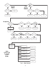
There are either three or four compressors divided among
two refrigeration circuits in the unit. Circuit A always contains
two compressors (A1,A2). Circuit B has either one or two
compressors (B1,B2). There may be a minimum load valve
(MLV), which, if present, is only associated with circuit A. The
decision as to which compressor should be turned on or off is
decided by the compressor’s availability followed by a pre-
ferred staging order.
NOTE: Configuration of the machine control type (C.TYP)
has no effect on whether a unit has a VFD or just a supply fan
installed for static pressure control. No matter what the control
type is, it is possible to run the unit in either CV or VAV mode
provided there are enough stages to accommodate lower air
volumes for VAV operation. Refer to the section on static pres-
sure control for information on how to set up the unit for the
type of supply fan control desired.
SETTING UP THE SYSTEM
Machine Control Type (
Configuration
UNIT
C.TYP) —
The most important cooling control configuration is located
under Configuration
UNIT.
This configuration defines the method and control source
responsible for selecting a cooling mode. The configuration
also determines the method by which compressors are staged.
Control types are:
• C.TYP = 1 (VAV-RAT) and C.TYP = 2 (VAV-SPT)
Both of these configurations refer to standard VAV opera-
tion. If the control is occupied, the supply fan is run continu-
ously and return-air temperature will be used for both in the
determination of the selection of a cooling mode. VAV-SPT
differs from VAV-RAT only in that during the unoccupied
period, space temperature will be used instead of return-air
temperature to start the fan for ten minutes before the
return-air temperature is allowed to call out any mode.
• C.TYP = 3 (TSTAT-MULTI)
This configuration will force the control to monitor the ther-
mostat inputs to make a determination of mode. Unlike tra-
ditional 2-stage thermostat control, the unit is allowed to use
multiple stages of cooling control and perform VAV style
operation. The control will be able to call out a LOW
COOL or a HIGH COOL mode and maintain a low or high
cool supply air set point.
• C.TYP = 4 (TSTAT-2 STG)
This configuration will force the control to monitor the ther-
mostat inputs to make a determination of mode.
• C.TYP = 5 (SPT-MULTI)
This configuration will force the control to monitor a space
temperature sensor to make a determination of mode. Un-
like traditional 2-stage space temperature control, the unit is
allowed to use multiple stages of cooling control and per-
form VAV style operation. The control will be able to call