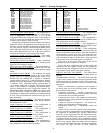
35
HVAC Mode — TEMPERING HICOOL
(12) — The econ-
omizer is at minimum vent position but the combination of the
outside-air temperature and the economizer position has
dropped the supply-air temperature below the tempering cool
set point. Staged gas heat is used to temper the ventilation air.
HVAC Mode — VENT
(13) — This is a normal operation
mode where no heating or cooling is required and outside air is
being delivered to the space to control IAQ levels.
HVAC Mode — LOW COOL
(14) — This is a normal cool-
ing mode where a low cooling demand is required.
HVAC Mode — HIGH COOL
(15) — This is a normal cool-
ing mode where a high cooling demand is required.
HVAC Mode — LOW HEAT
(16) — The unit will be in low
heating demand mode using either gas or electric heat.
HVAC Mode — HIGH HEAT
(17) — The unit will be in
high heating demand mode using either gas or electric heat.
HVAC Mode — UNOCC. FREE COOL (18)
— In this
mode the unit will operate in cooling but will be using the
economizer for free cooling. Entering this mode will depend on
the status of the outside air. The unit can be configured for out-
side air changeover, differential dry bulb changeover, outside
air enthalpy changeover, differential enthalpy changeover, or a
custom arrangement of enthalpy/dewpoint and dry bulb. See
the Economizer section for further details.
HVAC Mode — FIRE SHUT DOWN
(19) — The unit has
been stopped due to a fire shutdown input (FSD) or two or
more of the fire control modes, purge, evacuation, or pressur-
ization have been requested simultaneously.
HVAC Mode — PRESSURIZATION
(20) — The unit is in
the special fire pressurization mode where the supply fan is on,
the economizer damper is open and the power exhaust fans are
off. This mode is started by the Fire Pressurization (PRES) in-
put which can be found in the INPUT
FIRE sub-menu.
HVAC Mode — EVACUATION
(21) — The unit is in the
special Fire Evacuation mode where the supply fan is off, the
economizer damper is closed and the power exhaust fans are
on. This mode is started by the Fire Evacuation (EVAC) input
which can be found in the INPUT
FIRE sub-menu.
HVAC Mode — SMOKE PURGE
(22) — The unit is in the
special Fire Purge mode where the supply fan is on, the econo-
mizer damper is open and the power exhaust fans are on. This
mode is started by the Fire Evacuation (PURG) input which
can be found in the INPUT
FIRE sub-menu.
HVAC Mode — DEHUMIDIFICATION (23)
— The unit is
operating in Dehumidification mode.
HVAC Mode — REHEAT
(24) — The unit is operating in
reheat mode.
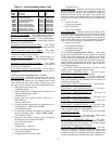
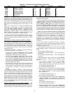
Unit Configuration Submenu — The UNIT sub-
menu under the Configuration mode of the local display
contains general unit configuration items. The sub-menu which
contains these configurations is located at the local display un-
der Configuration
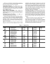
UNIT. See Table 43.
Machine Control Type (
C.TYP) — This configuration de-
fines the control type and control source responsible for select-
ing a cooling, heating, or vent mode and in determining the
method by which compressors are staged. The control types
are:
• C.TYP = 1 (VAV-RAT) and C.TYP = 2 (VAV-SPT)
Both of these configurations refer to standard VAV opera-
tion. If the control is occupied, the supply fan is run
continuously and return-air temperature will be used in the
determination of the selection of a cooling mode. VAV-SPT
differs from VAV-RAT only in that during the unoccupied
period, space temperature will be used instead of return-air
temperature to start the fan for 10 minutes to establish an
accurate return-air temperature before the return-air temper-
ature is allowed to call out any mode.
• C.TYP = 3 (TSTAT-MULTI)
This configuration will force the control to monitor the ther-
mostat inputs to make a determination of mode. Unlike
traditional 2-stage thermostat control, the unit is allowed to
use multiple stages of cooling control and perform VAV-
type operation. The control will be able to call out a LOW
COOL or a HIGH COOL mode and maintain a low or high
cool supply air set point.
• C.TYP = 4 (TSTAT-2 STG)
This configuration will force the control to monitor the ther-
mostat inputs to make a determination of mode and allow
only 2 stages of control for both heating and cooling.
• C.TYP = 5 (SPT-MULTI)
This configuration will force the control to monitor a space
temperature sensor to make a determination of mode.
Unlike traditional 2-stage space temperature control, the
unit is allowed to use multiple stages of cooling control and
perform VAV-type operation. The control will be able to call
out a LOW COOL or a HIGH COOL mode and maintain a
low or high cool supply air set point.
• C.TYP = 6 (SPT-2 STG)
This configuration will force the control to monitor the
space temperature sensor to make a determination of mode
and allow 2 stages of control for both heating and cooling.
FAN MODE (CV.FN) — The Fan Mode configuration can be
used for machine control types (Configuration
UNIT
C.TYP) 3, 4, 5, and 6. The Fan Mode variable
establishes the operating sequence for the supply fan during
occupied periods. When set to 1 (Continuous), the fan will
operate continuously during occupied periods. When set to 0
(Automatic), the fan will run only during a heating or cooling
mode.
REMOTE SWITCH CONFIG (RM.CF) — The remote switch
input is connected to TB6 terminals 1 and 3. This switch can be
used for several remote control functions. Please refer to the
Remote Control Switch Input section for details on its use and
operation.
CEM MODEL INSTALLED (CEM) — This configuration in-
structs the control to communicate with the controls expansion
module (CEM) over the Local Equipment Network (LEN) when
set to Yes. When the unit is configured for certain sensors and
configurations, this option will be set to Yes automatically.
The sensors and configurations that automatically turn on
this board are:
Configuration
UNIT
SFS.M = 1 (Supply Fan Status
Switch Monitoring)
Configuration
EDT.R
RES.S = Enable (4 to 20 mA Sup-
ply Air Reset Sensor Enable)
Configuration
DMD.L
DM.L.S = 1 (2 SWITCHES)
(Demand Limiting using 2 discrete switches)
Configuration
DMD.L
DM.L.S = 2 (4-20 MA CTRL)
(Demand Limiting using a 4 to 20 mA sensor)
Configuration
IAQ
AQ.CF
IQ.I.C = 1 (IAQ DISCRETE)
(IAQ discrete switch control)
Configuration
IAQ
AQ.CF
IQ.I.C = 2 (IAQ DISC.OVR)
(IAQ discrete switch “override” control)
Configuration
IAQ
AQ.CF
OQ.A.C = 1 (OAQ SENS-
DAQ) (Outdoor Air Quality Sensor)
Configuration
IAQ
AQ.CF
OQ.A.C = 2 (4-20 NO
DAQ) (4 to 20 mA sensor, no DAQ)
Temperature Compensated Start Cooling Factor (
TCS.C) —
This factor is used in the equation of the Temperature Compen-
sated Start Time Bias for cooling. Refer to the Temperature


