


175
APPENDIX E — UPC OPEN CONTROLLER (cont)
Configuring the UPC Open Controller's Prop-
erties —
The UPC Open device and ComfortLink™ con-
trols must be set to the same CCN Address (Element) number
and CCN Bus number. The factory default settings for CCN
Element and CCN Bus number are 1 and 0 respectively.
If modifications to the default Element and Bus number are
required, both the ComfortLink and UPC Open configurations
must be changed.
The following configurations are used to set the CCN Ad-
dress and Bus number in the ComfortLink controls. These con-
figurations can be changed using the scrolling marquee display
or accessory Navigator handheld device.
Configuration→CCN→CCN.A (CCN Address)
Configuration→CCN→CCN.B (CCN Bus Number)
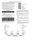
The following configurations are used to set the CCN Ad-
dress and Bus Number in the UPC Open controller. These con-
figurations can be changed using the accessory BACview
6
display.
Navigation: BACview→CCN
Home: Element Comm Stat
Element: 1
Bus: 0
Troubleshooting — If there are problems wiring or ad-
dressing the UPC Open controller, contact Carrier Technical
Support.
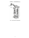
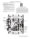
COMMUNICATION LEDS
— The LEDs indicate if the
controller is communicating with the devices on the network.
See Tables E and F. The LEDs should reflect communication
traffic based on the baud rate set. The higher the baud rate the
more solid the LEDs become. See Fig. B for location of LEDs
on UPC Open module.
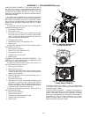
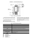
REPLACING THE UPC OPEN BATTERY — The UPC
Open controller's 10-year lithium CR2032 battery provides a
minimum of 10,000 hours of data retention during power
outages.
Remove the battery from the controller, making note of the
battery's polarity. Insert the new battery, matching the battery's
polarity with the polarity indicated on the UPC Open
controller.
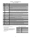
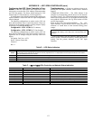
Table E — LED Status Indicators
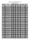
Table F — Run and Error LEDs Controller and Network Status Indication
IMPORTANT: Power must be ON to the UPC Open when
replacing the battery, or the date, time, and trend data will
be lost.
LED STATUS
Power
Lights when power is being supplied to the controller. The UPC Open controller is protected by internal solid-state polyswitches on
the incoming power and network connections. These polyswitches are not replaceable and will reset themselves if the condition
that caused the fault returns to normal.
Rx Lights when the controller receives data from the network segment; there is an Rx LED for Ports 1 and 2.
Tx Lights when the controller transmits data to the network segment; there is an Rx LED for Ports 1 and 2.
Run Lights based on controller status. See Table F.
Error Lights based on controller status. See Table F.
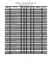
RUN LED ERROR LED STATUS
2 flashes per second Off Normal
2 flashes per second 2 flashes, alternating with Run LED Five minute auto-restart delay after system error
2 flashes per second 3 flashes, then off Controller has just been formatted
2 flashes per second 1 flash per second Controller is alone on the network
2 flashes per second On Exec halted after frequent system errors or control programs halted
5 flashes per second On Exec start-up aborted, Boot is running
5 flashes per second Off Firmware transfer in progress, Boot is running
7 flashes per second 7 flashes per second, alternating with Run LED Ten second recovery period after brownout
14 flashes per second 14 flashes per second, alternating with Run LED Brownout