


101
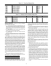
T705 (Limit Switch Thermistor Failure)
— A failure (the sen-
sor is outside the range of –40 F to 240 F) of this thermistor
(Temperatures
AIR.T
S.G.LM) will cause an alert to occur
and a disabling of the limit switch monitoring function for the
staged gas control board (SCB). Recovery is automatic.
Reason for failure may be due to faulty wiring, a faulty
thermistor, or a damaged input on the staged gas control board
(SCB).
MAJOR SYSTEM COMPONENTS
General —
The 48/50A Series package rooftop units with
electric cooling and with gas heating (48A units) or electric
cooling and electric heating (50A units) contain the
ComfortLink™ electronic control system that monitors all
operations of the rooftop. The control system is composed of
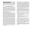
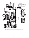
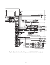
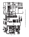
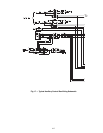
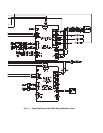
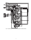
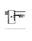
several components as listed below. See Fig. 15-23 for typical
control and power component schematics. Figures 24 and 25
show the layout of the control box, unit, and thermistor and
transducer locations.
Factory-Installed Components
MAIN BASE BOARD (MBB) — See Fig 26. The MBB is
the center of the ComfortLink control system. The MBB con-
tains the major portion of the operating software and controls
the operation of the unit. The MBB has 22 inputs and 11 out-
puts. See Table 115 for the inputs and output assignments. The
MBB also continuously monitors additional data from the
optional ECB1, ECB2, SCB, and CEM boards through the
LEN communications port. The MBB also interfaces with the
Carrier Comfort Network
®
system through the CCN communi-
cations port. The board is located in the main control box.
ECONOMIZER BOARD (ECB1) — The ECB1 controls the
economizer actuator and the power exhaust fans. The ECB1
operates the economizer motor using a digital communication
signal that also provides status and diagnostics for the econo-
mizer motor. See Fig. 27. The ECB1 also controls the operation
of the power exhaust motors and provides up to 6 stages of dig-
itally sequenced power exhaust either based on the economizer
motor position or the building pressure. The board has 4 inputs
and 6 outputs. Additionally, ECB1 provides an output that will
send a 4 to 20 mA signal to a field-installed VFD power ex-
haust accessory. Details can be found in Table 116. The ECB1
board is located in an auxiliary box located at the end of the
unit behind the filter access door. The board also contains
a second LEN port than can be used with the accessory
Navigator™ display.
VAV BOARD (ECB2) — The VAV board (which is the same
hardware as the ECB1) is used to control the supply fan on
VAV units. See Fig. 27. It sends a 4 to 20 mA signal to the VFD
based on a supply duct pressure sensor connected to the board.
The board also accepts a signal from another pressure sensor
that monitors building pressure and controls the operation of
the optional modulating power exhaust motors. The board will
also be used on CV units with the optional building pressure
control feature and modulating power exhaust. This board is
also used to control a digitally controlled hot gas bypass sole-
noid with an integral orifice for use in low load applications.
This board is located in the auxiliary control box. Input and
output assignments are summarized in Table 117.
STAGED GAS HEAT BOARD (SCB) — When optional
staged gas heat is used on CV and VAV units, the SCB board is
installed and controls operation of the gas valves. See Fig. 28.
The SCB also provides additional sensors for monitoring of the
supply-air temperature. This board is located in the gas heat
section of the unit. The inputs and outputs are summarized in
Table 118.
CONTROL EXPANSION MODULE (CEM) — The optional
CEM (also available as an accessory) is used to accept inputs
for additional sensors or control sequence switches, including:
• smoke control mode field switches
• VAV Supply Air Temperature Set Point reset using an exter-
nal 4 to 20 mA signal
• outdoor air CO
2
sensor (for supply duct pressure reset using
an eternal 4 to 20 mA signal)
• external fan status pressure switch input (CV units)
• demand limit sequence proportional signal or discrete
switches
The CEM board is located in the main control box. See
Fig. 29. The inputs and outputs are summarized in Table 119.
INTEGRATED GAS CONTROL (IGC) — One IGC is pro-
vided with each bank of gas heat exchangers (2 used on the size
020-050 units and 3 on size 051 and 060 units). The IGC
controls the direct spark ignition system and monitors the
rollout switch, limit switches, and induced-draft motor Hall
Effect switch. The IGC is equipped with an LED (light-
emitting diode) for diagnostics. See Table 120.
COMPRESSOR PROTECTION BOARD (CS) — This board
monitors the status of the compressor by sensing the current
flow to the compressors and then provides digital status signal
to the MBB.