


167
APPENDIX C — VFD INFORMATION (cont)
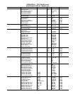
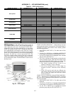
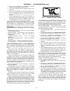
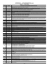
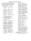
Table D — Alarm Codes
*This alarm is not indicated by a relay output, even when the relay output is configured to indicate alarm conditions, parameter 1401 RELAY OUT-
PUT = 5 (ALARM) or 16 (FLT/ALARM).
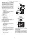
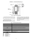
Check the heat sink as follows (when necessary):
1. Remove power from drive.
2. Remove the cooling fan.
3. Blow clean compressed air (not humid) from bottom to top
and simultaneously use a vacuum cleaner at the air outlet
to trap the dust. If there a risk of the dust entering adjoining
equipment, perform the cleaning in another room.
4. Replace the cooling fan.
5. Restore power.
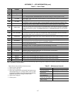
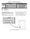
Table E — Maintenance Intervals
ALARM
CODE
ALARM NAME
IN PANEL
DESCRIPTION AND RECOMMENDED CORRECTIVE ACTION
2001 —
Reserved
2002 —
Reserved
2003 —
Reserved
2004 DIR LOCK
The change in direction being attempted is not allowed. Do not attempt to change the direction of motor rota-
tion, or Change parameter 1003 DIRECTION to allow direction change (if reverse operation is safe).
2005 I/O COMM
Field bus communication has timed out. Check fault setup (3018 COMM FAULT FUNC and 3019 COMM
FAULT TIME). Check communication settings (Group 51 or 53 as appropriate). Check for poor connections
and/or noise on line.
2006 AI1 LOSS
Analog input 1 is lost, or value is less than the minimum setting. Check input source and connections. Check
the parameter that sets the minimum (3021) and the parameter that sets the Alarm/Fault operation (3001).
2007 AI2 LOSS
Analog input 2 is lost, or value is less than the minimum setting. Check input source and connections. Check
parameter that sets the minimum (3022) and the parameter that sets the Alarm/Fault operation (3001).
2008 PANEL LOSS
Panel communication is lost and either the VFD is in local control mode (the control panel displays HAND), or
the VFD is in remote control mode (AUTO) and is parameterized to accept start/stop, direction or reference
from the control panel. To correct, check the communication lines and connections, Parameter 3002 PANEL
LOSS, and parameters in groups 10 COMMAND INPUTS and 11 REFERENCE SELECT (if drive operation
is REM).
2009 —
Reserved
2010 MOT OVERTEMP
Motor is hot, based on either the VFD estimate or on temperature feedback. This alarm warns that a Motor
Overload fault trip may be near. Check for overloaded motor. Adjust the parameters used for the estimate
(3005 through 3009). Check the temperature sensors and Group 35 parameters.
2011 UNDERLOAD
Motor load is lower than expected. This alarm warns that a Motor Underload fault trip may be near. Check
that the motor and drive ratings match (motor is NOT undersized for the drive). Check the settings on param-
eters 3013 to 3015.
2012 MOTOR STALL
Motor is operating in the stall region. This alarm warns that a Motor Stall fault trip may be near.
2013* AUTORESET
This alarm warns that the drive is about to perform an automatic fault reset, which may start the motor. To
control automatic reset, use parameter group 31 (AUTOMATIC RESET).
2014* AUTOCHANGE
This alarm warns that the PFA autochange function is active. To control PFA, use parameter group 81 (PFA)
and the Pump Alternation macro.
2015 PFA INTERLOCK
This alarm warns that the PFA interlocks are active, which means that the drive cannot start any motor (when
Autochange is used), or a speed regulated motor (when Autochange is not used).
2016 — Reserved
2017* OFF BUTTON This alarm indicates that the OFF button has been pressed.
2018* PID SLEEP
This alarm warns that the PID sleep function is active, which means that the motor could
accelerate when the PID sleep function ends. To control PID sleep, use parameters
4022 through 4026 or 4122 through 4126.
2019 ID RUN The VFD is performing an ID run.
2020 OVERRIDE Override mode is activated.
2021
START ENABLE 1
MISSING
This alarm warns that the Start Enable 1 signal is missing. To control Start Enable 1 function, use parameter
1608. To correct, check the digital input configuration and the communication settings.
2022
START ENABLE 2
MISSING
This alarm warns that the Start Enable 2 signal is missing. To control Start Enable 2 function, use parameter
1609. To correct, check the digital input configuration and the communication settings.
2023 EMERGENCY STOP Emergency stop is activated.
MAINTENANCE INTERVAL
Heat Sink Temperature
Check and Cleaning
Every 6 to 12 months (depending
on the dustiness of the environment)
Main Cooling Fan
Replacement
Every five years
Internal Enclosure Cooling
Fan Replacement
Every three years
Capacitor Change
(Frame Size R5 and R6)
Every ten years
HVAC Control Panel
Battery Change
Every ten years