


36
Compensated Start section for more information. A setting of
0 minutes indicates Temperature Compensated Start in Cooling
is not permitted.
Temperature Compensated Start Heating Factor
(TCS.H) —
This factor is used in the equation of the Temperature Compen-
sated Start Time Bias for heating. Refer to the Temperature
Compensated Start section for more information. A setting of
0 minutes indicates Temperature Compensated Start in Heating
is not permitted.
Fan Fail Shuts Downs Unit (
SFS.S) — This configuration
will determine whether the unit should shut down on a supply
fan status fail or simply alert the condition and continue to run.
If set to YES, then the control will shut down the unit and send
out an alarm if supply fan status monitoring fails. If set to NO,
the control will not shut down the unit if supply fan status mon-
itoring fails but the control will send out an alert.
Fan Status Monitoring (
SFS.M) — This configuration selects
the type of fan status monitoring to be performed.
0 - NONE — No switch or monitoring
1 - SWITCH — Use of the fan status switch
2 - SP RISE — Monitoring of the supply duct pressure.
VAV Unoccupied Fan Retry Time (
VAV.S) — Machine con-
trol types 1 and 2 (VAV-RAT,VAV-SPT) monitor the return-air
temperature during unoccupied periods to determine if there is
a valid demand for heating or cooling before initiating an unoc-
cupied heating or cooling mode. If the routine runs but con-
cludes a valid demand condition does not exist, then the pro-
cess is not permitted for the period of time defined by this con-
figuration. Reducing this value allows a more frequent re-
sampling process. Setting this value to zero will prevent any
sampling sequence.
Unit Size (
SIZE) — There are several unit sizes (tons) for the
A Series control. Make sure this configuration matches the size
called out by the model number of the unit. This is important as
the cooling stage tables are directly determined based on this
configuration.
Discharge Pressure Transducers (
DP.XR) — This configuration
configures the unit for use with discharge pressure transducers.
The 48/50A2,A3,A4,A5 units will be automatically configured
for discharge pressure transducers and DP.XR should be set to
Ye s.
Suction Pressure Transducer Type (
SP.XR) — This configu-
ration specifies the type of suction pressure transducer that is
being used. Set SP.XR to 0 for support of a pressure transducer
with a range of 0 to 135 psig. Set SP.XR to 1 for support of a
pressure transducer with a range of 0 to 200 psig.
NOTE: The 48/50A2,A3,A4,A5 units do not require a change
to the SP.XR factory default setting.
Refrigerant Type (
RFG.T) — This configuration specifies the
type of refrigerant used in the unit. Configuration RFG.T is set
to 0 if the refrigerant used is R-22. Configuration RFG.T is set
to 1 if the refrigerant used is R-410A. Do not change this
setting.
Condenser Type (
CND.T) — This configuration specifies the
type of condenser installed in the unit. Configuration CND.T is
set to 0 if the condenser is a round tube, plate fin coil (RTPF).
Configuration CND.T is set to 1 if the condenser is a micro-
channel heat exchanger coil (MCHX).
MAT Calc Config (
MAT.S) — This configuration gives the
user three options in the processing of the mixed-air tempera-
ture (MAT) calculation:
• MAT.S = 0
There will be no MAT calculation.
• MAT.S = 1
The control will attempt to learn MAT over time. Any time
the system is in a vent mode and the economizer stays at a
particular position for long enough, MAT is set to equal
EDT. Using this, the control has an internal table whereby it
can more closely determine the true MAT value.
• MAT.S = 2
The control will not attempt to learn MAT over time.
To calculate MAT linearly, the user should reset the MAT
table entries by setting MAT.R to YES. Then set MAT.S = 2.
The control will calculate MAT based on the position of the
economizer, outside-air temperature, and return-air
temperature.
To freeze the MAT table entries, let the unit run with MAT.S
= 1. Once sufficient data has been collected, change MAT.S
= 2. Do not reset the MAT table.
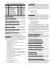
Table 43 — Unit Configuration
ITEM EXPANSION RANGE UNITS CCN POINT DEFAULTS
UNIT UNIT CONFIGURATION
C.TYP Machine Control Type 1 - 6 CTRLTYPE 4
CV.FN Fan Mode (0=Auto, 1=Cont) 0 - 1 FAN_MODE 1
RM.CF Remote Switch Config 0 - 3 RMTINCFG 0
CEM CEM Module Installed Yes/No CEM_BRD No
TCS.C Temp.Cmp.Strt.Cool Factr 0 - 60 min TCSTCOOL 0
TCS.H Temp.Cmp.Strt.Heat Factr 0 - 60 min TCSTHEAT 0
SFS.S Fan Fail Shuts Down Unit Yes/No SFS_SHUT No
SFS.M Fan Stat Monitoring Type 0 - 2 SFS_MON 0
VAV.S VAV Unocc.Fan Retry Time 0 - 720 min SAMPMINS 50
SIZE Unit Size (20-60) 20 - 60 UNITSIZE 20
DP.XR Discharge Press. Transducers Yes/No DP_TRANS No
SP.XR Suct. Pres. Trans. Type 0 - 1 SPXRTYPE 0
RFG.T REFRIG: 0=R22, 1=R410A 0 - 1 REFRIG_T Unit dependent
CND.T CND HX TYP: 0=RTPF, 1=MCHX 0 - 1 COILTYPE Unit dependent
MAT.S MAT Calc Config 0 - 2 MAT_SEL 1
MAT.R Reset MAT Table Entries? Yes/No MATRESET No
MAT.D MAT Outside Air Default 0-100 % MATOADOS 20
ALTI Altitude……..in feet: 0 - 60000 ALTITUDE 0
DLAY Startup Delay Time 0 - 900 sec DELAY 0
STAT TSTAT-Both Heat and Cool Yes/No TSTATALL No
AUX.R Auxiliary Relay Config 0 - 3 AUXRELAY 0
SENS INPUT SENSOR CONFIG
SPT.S Space Temp Sensor Enable/Disable SPTSENS Disable
SP.O.S Space Temp Offset Sensor Enable/Disable SPTOSENS Disable
SP.O.R Space Temp Offset Range 1 - 10 SPTO_RNG 5
RRH.S Return Air RH Sensor Enable/Disable RARHSENS Disable
FLT.S Filter Stat.Sw.Enabled ? Enable/Disable FLTS_ENA Disable