


49
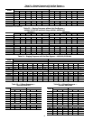
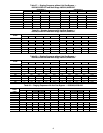
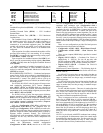
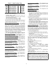
Table 63 — Demand Limit Configuration
The relevant configurations for this type of demand limiting
are:
Loadshed Group Number (SH.NM) — CCN Loadshed Group
number
Loadshed Demand Delta (SH.DL) — CCN Loadshed
Demand Delta
Maximum Loadshed Time (SH.TM) — CCN Maximum
Loadshed time
The Loadshed Group Number (SH.NM) corresponds to
the loadshed supervisory device that resides elsewhere on
the CCN network and broadcasts loadshed and redline
commands to its associated equipment parts. The SH.NM
variable will default to zero which is an invalid group num-
ber. This allows the loadshed function to be disabled until
configured.
Upon reception of a redline command, the machine will be
prevented from starting if it is not running. If it is running,
then DEM.L is set equal to the current running cooling capac-
ity (Run Status
COOL
C.CAP).
Upon reception of a loadshed command, the DEM.L vari-
able is set to the current running cooling capacity (Run Status
COOL
C.CAP) minus the configured Loadshed Demand
Delta (SH.DL).
A redline command or loadshed command will stay in
effect until a Cancel redline or Cancel loadshed command is
received, or until the configurable Maximum Loadshed time
(SH.TM) has elapsed.
HEAD PRESSURE CONTROL — Condenser head pressure
control for the 48/50A series rooftops is controlled directly by
the unit, except when the unit is equipped and configured for
Motormaster® V control. The control is able to cycle up to
three stages of outdoor fans (see Table 64) to maintain accept-
able head pressure.
For 48/50AJ,AK,AW,AY units, fan stages will react to satu-
rated condensing temperature (SCT) sensors (Tempera-
tures
REF.T
SCT.A and SCT.B) which are connected to
the condenser coils in circuit A and B. The control converts the
temperatures to the corresponding refrigerant pressures (Pres-
sures
REF.P
DP.A and DP.B).
For 48/50A2,A3,A4,A5 units, fan stages react to discharge
pressure transducers (DPT) (Pressures
REF.P
DP.A and
DP.B) which are connected to the compressor discharge piping
in circuit A and B. The control converts the pressures to the
corresponding saturated condensing temperatures (Tempera-
tures
REF.T
SCT.A and SCT.B).
Unit size (Configuration
Unit
Size), refrigerant type
(Configuration
Unit
RFG.T), and condenser heat ex-
changer type (Configuration
Unit
CND.T) are used to de-
termine if the second stage fans are configured to respond to a
particular refrigerant circuit (independent control) or both re-
frigerant circuits (common control). The 48/50A2,A3,
A4,A5060 units with microchannel (MCHX) condenser heat
exchangers are the only units that utilize independent fan
controls.
If the unit is equipped with the accessory Motormaster V
control, the Motormaster installed configuration
(Configuration
COOL
M.M.) must be set to YES if the
unit size (Configuration
Unit
SIZE) is 60 tons and the
condenser heat exchanger type (Configuration
Unit
CND.T) is RTPF (round tube plate fin). This is because the
condenser fan relay A (MBB Relay 6) output must be ener-
gized to enable the Motormaster V control and must not be
turned off by the head pressure control algorithm. The size 60
ton unit with RTPF condenser heat exchangers offers 3 stages
of head pressure control and is the one case where condenser
fan relay A may be requested off during head pressure control
operation. By configuring M.M. to YES, the control is instruct-
ed not to turn off the relay to attempt 3 stages of head pressure
control.
There are two configurations provided for head pressure
control that can be found at the local display:
• Configuration
COOL
M.M. – Motor Master Control?
• Configuration
COOL
HPSP – Head Pressure Set-
point
There are two outputs (MBB Relays) provided to control
head pressure:
• Outputs
FANS
CD.F.A – Condenser Fan Circuit A
(MBB Relay 6 - OFC1,4). For size 60 ton units with
MCHX condensers, MBB – Relay 6 drives OFC4 and com-
pressor contactor B1 or B2 auxiliary contacts drive OFC1.
• Outputs
FANS
CD.F.B – Condenser Fan Circuit B
(MBB Relay 5 - OFC2)
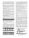
Head Pressure Control Operation
— The following logic de-
scribes the head pressure control routines for the unit sizes out-
lined in Table 64.
For 020 to 035 size units, there are two outdoor fans that are
common to both refrigerant circuits. The control cycles two
stages of outdoor fans, one fan per stage, to maintain accept-
able head pressure.
For 036 to 050 size units, there are four outdoor fans that are
common to both refrigerant circuits. The control cycles two
stages of outdoor fans, two fans per stage, to maintain accept-
able head pressure.
For 051 and 060 size units – There are six outdoor fans that
are common to both refrigerant circuits (size 060 MCHX units
have 4 fans). The control cycles three stages of outdoor fans,
two fans for stage one, four fans for stage two, and six fans for
stage three to maintain acceptable head pressure.
When a compressor has been commanded on, then con-
denser fan A (MBB Relay 6) will be energized (CD.F.A =
ON). Condenser fan A will remain on until all compressors
have been commanded off. If the highest active circuit SCT is
above the HPSP or if OAT is greater than 75 F then condenser
fan B (MBB Relay 5) will be energized (CD.F.B = ON). Con-
denser fan B will remain on until all compressors have been
commanded off, or the highest active circuit SCT drops 40 F
below the HPSP for greater than 2 minutes and OAT is less
than 73 F.
NOTE: For size 60 units with RTPF condenser heat exchang-
ers not configured for Motormaster control, the control stages
down differently than the other units. For these units, the con-
trol will first turn off condenser fan relay A. After 2 minutes,
the control will turn off relay B and turn back on relay A.
ITEM EXPANSION RANGE UNITS CCN POINT DEFAULT
DMD.L DEMAND LIMIT CONFIG.
DM.L.S Demand Limit Select 0 - 3 DMD_CTRL 0
D.L.20 Demand Limit at 20 ma 0 - 100 % DMT20MA 100
SH.NM Loadshed Group Number 0 - 99 SHED_NUM 0
SH.DL Loadshed Demand Delta 0 - 60 % SHED_DEL 0
SH.TM Maximum Loadshed Time 0 - 120 min SHED_TIM 60
D.L.S1 Demand Limit Sw.1 Setpt. 0 - 100 % DLSWSP1 80
D.L.S2 Demand Limit Sw.2 Setpt. 0 - 100 % DLSWSP2 50