


59
Therefore, the amount to add to the economizer’s
ECONOMIN configuration is: (0.5/0.75) x (50-20) = 20%. In
effect, for the positioning of the economizer, ECONOMIN
would now be replaced by ECONOMIN + 10%.
Static Pressure PID Config (
S.PID) — Static pressure PID
configuration can be accessed under this heading in the Con-
figuration
SP submenu. Under most operating conditions the
control PID factors will not require any adjustment and the
factory defaults should be used. If persistent static pressure
fluctuations are detected, small changes to these factors may
improve performance. Decreasing the factors generally reduce
the responsiveness of the control loop, while increasing the
factors increase its responsiveness. Note the existing settings
before making changes, and seek technical assistance from
Carrier before making significant changes to these factors.
Static Pressure PID Run Rate (S.PID
SP.TM) — This is the
number of seconds between duct static pressure readings taken
by the ComfortLink™ PID routine.
Static Pressure Proportional Gain (S.PID
SP.P) — This is
the proportional gain for the static pressure control PID control
loop.
Static Pressure Integral Gain (S.PID
SP.I) — This is the
integral gain for the static pressure control PID control loop.
Static Pressure Derivative Gain (S.PID
SP.D) — This is the
derivative gain for the static pressure control PID control loop.
Static Pressure System Gain (S.PID
SP.SG) — This is the
system gain for the static pressure control PID control loop.
STATIC PRESSURE RESET OPERATION — The Com-
fortLink controls support the use of static pressure reset. The
Linkage Master terminal monitors the primary air damper posi-
tion of all the terminals in the system (done through LINKAGE
with the new ComfortID™ air terminals).
The Linkage Master then calculates the amount of supply
static pressure reduction necessary to cause the most open
damper in the system to open more than the minimum value
(60%) but not more than the maximum value (90% or negligi-
ble static pressure drop). This is a dynamic calculation, which
occurs every two minutes when ever the system is operating.
The calculation ensures that the supply static pressure is always
enough to supply the required airflow at the worst case termi-
nal but never more than necessary, so that the primary air
dampers do not have to operate with an excessive pressure
drop (more than required to maintain the airflow set point of
each individual terminal in the system).
As the system operates, if the most open damper opens
more than 90%, the system recalculates the pressure reduction
variable and the value is reduced. Because the reset value is
subtracted from the controlling set point at the equipment, the
pressure set point increases and the primary-air dampers close
a little (to less than 90%). If the most open damper closes to
less than 60%, the system recalculates the pressure reduction
variable and the value is increased. This results in a decrease in
the controlling set point at the equipment, which causes the
primary-air dampers to open a little more (to greater than 60%).
The rooftop unit has the static pressure set point
programmed into the CCN control. This is the maximum set
point that could ever be achieved under any condition. To
simplify the installation and commissioning process for the
field, this system control is designed so that the installer only
needs to enter a maximum duct design pressure or maximum
equipment pressure, whichever is less. There is no longer a
need to calculate the worst case pressure drop at design condi-
tions and then hope that some intermediate condition does not
require a higher supply static pressure to meet the load
conditions. For example, a system design requirement may be
1.2 in. wg, the equipment may be capable of providing
3.0 in. wg and the supply duct is designed for 5.0 in. wg. In this
case, the installer could enter 3.0 in. wg as the supply static
pressure set point and allow the air terminal system to dynami-
cally adjust the supply duct static pressure set point as required.
The system will determine the actual set point required de-
livering the required airflow at every terminal under the current
load conditions. The set point will always be the lowest value
under the given conditions. As the conditions and airflow set
points at each terminal change throughout the operating period,
the equipment static pressure set point will also change.
The CCN system must have access to a CCN variable
(SPRESET which is part of the equipment controller). In the
algorithm for static pressure control, the SPRESET value is
always subtracted from the configured static pressure set point
by the equipment controller. The SPRESET variable is always
checked to be a positive value or zero only (negative values are
limited to zero). The result of the subtraction of the SPRESET
variable from the configured set point is limited so that it
cannot be less than zero. The result is that the system will
dynamically determine the required duct static pressure based
on the actual load conditions currently in the space. This elimi-
nates the need to calculate the design supply static pressure set
point. This also saves the energy difference between the design
static pressure set point and the required static pressure.
Third Party 4 to 20 mA Input
— It is also possible to perform
static pressure reset via an external 4 to 20 mA signal connect-
ed to the CEM board where 4 mA corresponds to 0 in. wg of
reset and 20 mA corresponds to 3 in. wg of reset. The static
pressure 4 to 20 mA input shares the same input as the analog
OAQ sensor. Therefore, both sensors cannot be used at the
same time. To enable the static pressure reset 4 to 20 mA sen-
sor, set (Configuration
SP
SP.RS) to Enabled.
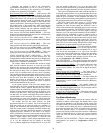
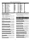
RELATED POINTS — These points represent static pressure
control and static pressure reset inputs and outputs. See Table 76.
Static Pressure mA (
SP.M) — This variable reflects the value
of the static pressure sensor signal received by the
ComfortLink™ controls. The value may be helpful in trouble-
shooting.
Static Pressure mA Trim (
SP.M.T) — This input allows a
modest amount of trim to the 4 to 20 mA static pressure trans-
ducer signal, and can be used to calibrate a transducer.
Static Pressure Reset mA (
SP.R.M) — This input reflects the
value of a 4 to 20 mA static pressure reset signal applied to
TB6 terminals 11 and 12 on the CEM board, from a third party
control system.
Static Pressure Reset (
SP.RS) — This variable reflects the
value of a static pressure reset signal applied from a CCN sys-
tem. The means of applying this reset is by forcing the value of
the variable SPRESET through CCN.
Supply Fan VFD Speed (
S.VFD) — This output can be used
to check on the actual speed of the VFD. This may be helpful
in some cases for troubleshooting.
Fan Status Monitoring
GENERAL — The A Series ComfortLink controls offer the
capability to detect a failed supply fan through either a duct
static pressure transducer or an accessory discrete switch. The
fan status switch is an accessory that allows for the monitoring
of a discrete switch, which trips above a differential pressure
drop across the supply fan. For any unit with a factory-installed
duct static pressure sensor, it is possible to measure duct
pressure rise directly, which removes the need for a differential
switch. All 48/50AK,AW,A3,A5 units with a factory-installed
supply fan VFD will have the duct static pressure sensor as
standard.
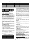
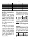
SETTING UP THE SYSTEM — The fan status monitoring
configurations are located in Configuration
UNIT. See
Table 77.