


61
modulate to the same control point (Sum Z) that is used to
control capacity staging. The advantage is lower compressor
cycling coupled with tighter temperature control. Setting this
option to No will cause the economizer, if it is able to provide
free cooling, to open to the Economizer Max. Position
(EC.MX) during mechanical cooling.
ECONOMIZER OPERATION — There are four potential
elements which are considered concurrently which determine
whether the economizer is able to provide free cooling:
1. Dry bulb changeover (outside-air temperature qualification)
2. Economizer switch (discrete control input monitoring)
3. Economizer changeover select (E.SEL economizer
changeover select configuration option)
4. Outdoor dewpoint limit check (requires an installed out-
door relative humidity sensor installed)
Dry Bulb Changeover (
OAT.L) — Outside-air temperature
may be viewed under Temperatures
AIR.T
OAT. The con-
trol constantly compares its outside-air temperature reading
against the high temperature OAT lockout (OAT.L). If the tem-
perature reads above OAT.L, the economizer will not be al-
lowed to perform free cooling.
Economizer Switch (
EC.SW) — The function of this switch
is determined by Configuration
ECON
EC.SW. The state
of the corresponding economizer input can be viewed under
Inputs
GEN.I
E.SW.
When set to EC.SW = 0, the switch is disabled. When set to
EC.SW = 1, the economizer switch functions to enable/disable
the economizer. When set to EC.SW = 2, the switch functions
as an IAQ override switch. This functions just like the discrete
IAQ input Inputs
AIR.Q
IAQ.I when Configuration
IAQ
AQ.CF
IQ.I.C=2 (IAQ Discrete Override). See the
Indoor Air Quality Control section for more information.
When Configuration
ECON
EC.SW=1 and Inputs
GEN.I
E.SW = No, free cooling will not be allowed.
Economizer Control Type (
E.TYP) — This configuration
should not be changed.
Economizer Changeover Select (
E.SEL) — The control is
capable of performing any one of the following changeover
types in addition to both the dry bulb lockout and the external
switch enable input:
E.SEL = 0 none
E.SEL = 1 Differential Dry Bulb Changeover
E.SEL = 2 Outdoor Enthalpy Changeover
E.SEL = 3 Differential Enthalpy Changeover
Differential Dry Bulb Changeover — As both return air and
outside air temperature sensors are installed as standard on
these units, the user may select this option, E.SEL = 1, to
perform a qualification of return and outside air in the enabling
and disabling of free cooling. If this option is selected and
outside-air temperature is greater than return-air temperature,
free cooling will not be allowed.
Outdoor Enthalpy Changeover — This option should be used
in climates with higher humidity conditions. The A Series
control can use an enthalpy switch or enthalpy sensor, or the
standard installed outdoor dry bulb sensor and an accessory
relative humidity sensor to calculate the enthalpy of the air.
Setting Configuration
ECON
E.SEL = 2 requires that
the user configure Configuration
ECON
OA.E.C, the
Outdoor Enthalpy Changeover Select, and install an outdoor
relative humidity sensor. Once the sensor is installed, enable
Configuration
ECON
ORH.S, the outdoor relative humid-
ity sensor configuration option.
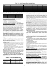
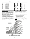
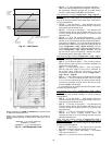
If the user selects one of the Honeywell curves, A,B,C or D,
then OA.E.C options 1-4 should be selected. See Fig. 10 for a
diagram of these curves on a psychrometric chart.
OA.E.C = 1 Honeywell A Curve
OA.E.C = 2 Honeywell B Curve
OA.E.C = 3 Honeywell C Curve
OA.E.C = 4 Honeywell D Curve
OA.E.C = 5 custom enthalpy curve
If the user selects OA.E.C = 5, a direct comparison of out-
door enthalpy versus an enthalpy set point is done. This out-
door enthalpy set point limit is configurable, and is called
Configuration
ECON
OA.EN.
Depending on what Configuration
ECON
OA.E.C is
configured for, if the outdoor enthalpy exceeds the Honeywell
curves or the outdoor enthalpy compare value (Configuration
ECON
OA.EN), then free cooling will not be allowed.
Differential Enthalpy Changeover — This option compares
the outdoor-air enthalpy to the return air enthalpy and chooses
the option with the lowest enthalpy. This option should be
used in climates with high humidity conditions. This option
uses both humidity sensors and dry bulb sensors to calculate
the enthalpy of the outdoor and return air. An accessory
outdoor air humidity sensor (ORH.S) and return air humidity
sensor (RRH.S) are used. The outdoor air relative humidity
sensor config (ORH.S) and return air humidity sensor config
(Configuration
UNIT
SENS
RRH.S) must be enabled.
Outdoor Dewpoint Limit Check
— If an outdoor relative
humidity sensor is installed, then the control is able to calculate
the outdoor air dewpoint temperature and will compare this
temperature against the outside air dewpoint temperature
limit configuration (Configuration
ECON
O.DEW). If the
outdoor air dewpoint temperature is greater than O.DEW, then
free cooling will not be allowed. Figure 11 shows a horizontal
limit line in the custom curve of the psychrometric chart. This
is the outdoor air dewpoint limit boundary.
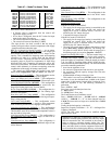
Fig. 10 — Psychrometric Chart for
Enthalpy Control
CONTROL CURVE
CONTROL POINT
(approx Deg) AT 50% RH
A 73
B 68
C 63
D 58